


35
An incorrectly aligned and tensioned belt can
sub stan tial ly shorten belt life or overload blow er and
motor bear ings, shortening their life ex pect an cy. A belt
tensioned too tightly can over load the motor electrical,
causing nui sance trip ping of the motor overloads and/or
motor fail ure and/or shaft fail ure.
Belt Replacement
Always replace belts as a set. Follow the steps below
to replace belts:
1. Release the tension on the belts by loos en ing the
ad just ing nuts on the fan motor.
2. Remove old belts and recheck the sheave align ment
with a straight edge.
3. Install the new belts on the sheaves.
Never place the belts on the sheaves by using a
screw driv er to pry the belt over the rim of the sheave.
This will damage the belts permanently.
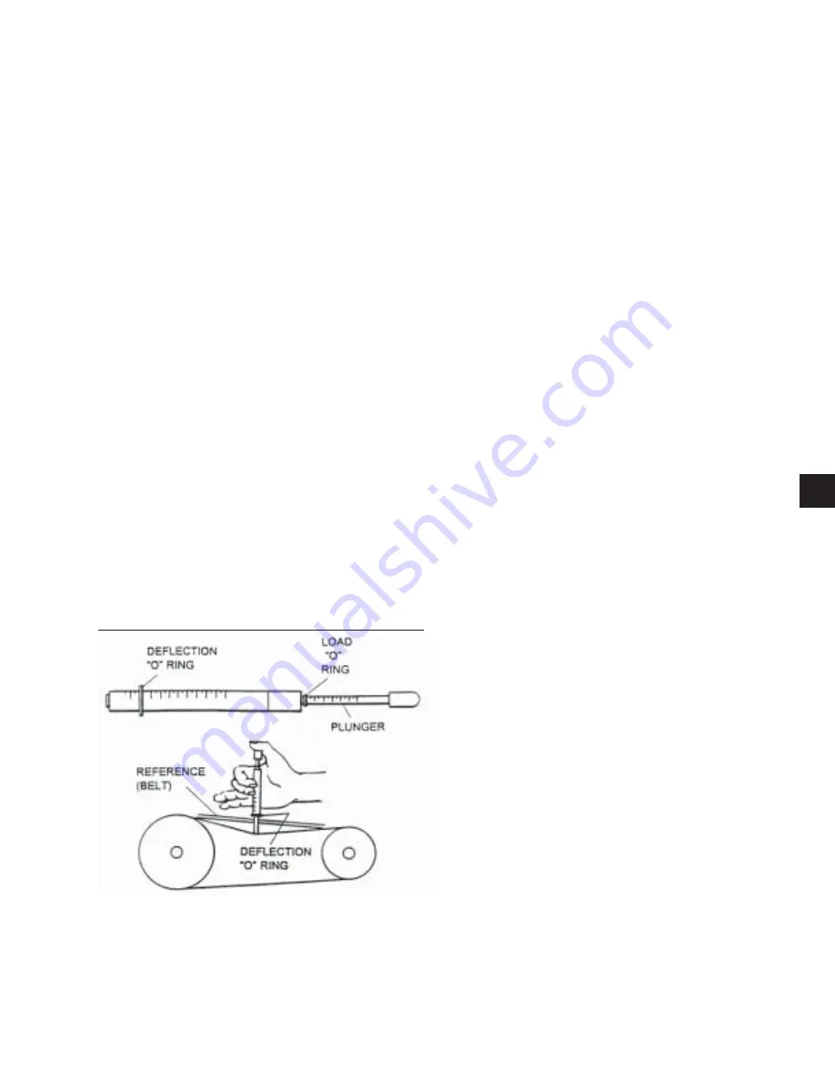
Belt Tensioning:
Belt tension information is included on the fan skid
data plate.
A Browning Belt tension gauge is used in Fig. 4 to
prop er ly tension belts.
Supply Fan
In the unlikely event that the supply fan would need to
be replaced the following procedure would need to be
followed:
1. In order to access the rear bearing and the set
screws for the wheel the Control / Supply section
of the unit must be separated from the Condenser
/ Compressor section. Form 145.05-FA1 is a de-
tailed instruction on the assembly of a Versecon
unit shipped segmented. Follow this instruction in
reverse to separate the unit into the two sections.
2. Thoroughly clean the shaft of all grease and rust
inhibitor. Be careful not to contaminate the bearing
grease. Use emery cloth to remove all rust or the
wheel may become “locked” to the shaft.
3. Loosen and remove the setscrews on both bear-
ing locking collars. Inspect and, if necessary,
replace.
4. Loosen and remove the two setscrews from the
Condenser / Compressor side of the supply fan
wheel.
5. Using a rubber mallet or brass bar, slowly drive the
shaft in one direction until the set screw marks on
the shaft are fully exposed. File the marks com-
pletely smooth. Drive the shaft in the opposite
direction and fi le smooth the setscrew marks.
6. To remove the key, use a rubber mallet or brass bar
to drive the shaft and wheel in one direction. Drive
the key in the opposite direction using a nail set or
smaller size key stock until the key is completely
free of the wheel. Be sure the key does not get
bent by allowing it to ride up the key way edge.
The slightest bend will prevent quick assembly.
Should it occur, replace the key stock.
7. Remove the shaft, supporting the weight of the
wheel. Do not allow the weight of the wheel to
be supported by only one bearing during the disas-
sembly process.
8. Remove the wheel through the side of the unit.
9. Reassembly in reverse order, centering the wheel
over the inlet cone. If bearings were removed or
replaced, be sure to reuse any shim stock found
between the mounting support / plate and bearing
housings.
FIG. 4 – BELT TENSIONING GAUGE
LD06354
4
JOHNSON CONTROLS
FORM 145.05-NOM2 (807)
Summary of Contents for YSCD
Page 10: ...10 JOHNSON CONTROLS FORM 145 05 NOM2 807 THIS PAGE INTENTIONALLY LEFT BLANK ...
Page 12: ...12 JOHNSON CONTROLS FORM 145 05 NOM2 807 THIS PAGE INTENTIONALLY LEFT BLANK ...
Page 38: ...38 JOHNSON CONTROLS FORM 145 05 NOM2 807 THIS PAGE INTENTIONALLY LEFT BLANK ...
Page 46: ...46 JOHNSON CONTROLS FORM 145 05 NOM2 807 THIS PAGE INTENTIONALLY LEFT BLANK ...
Page 105: ...105 JOHNSON CONTROLS FORM 145 05 NOM2 807 LD13009 8 FIG 11 WIRING DIAGRAM POWER CIRCUIT ...