


B2
-
23
IM 34M06H62-02E
2nd Edition : June 2008-00
Procedure for Enabling Controller and I/O Parameter Values
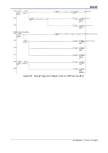
Figure B2.3 illustrates the procedure for enabling controller parameter and I/O parameter
values. Two I/O data registers, namely, SETUP and OPE, are used to enable settings,
whilst three relays (SETUP.R, CMDRDY, MDLRDY) and one input data register (STUS)
are used to check for successful execution.
Figure B2.3 Procedure for Enabling Controller Parameters and I/O Parameters
(1) Write a value of 1 to the SETUP register to transit to Setup mode and enable the OPE
register. To confirm that the module is now in Setup mode, check that the SETUP.R
relay has turned on. In Setup mode, the module suspends refreshing of data registers
and the control output value is “0%”.
(2) Write the new parameter value.
(3) Write to the OPE register an appropriate OPE value to initiate the process for
enabling the new parameter value.
(4) The module resets the CMDRDY relay as the setup process begins. It then resets the
OPE register to 0, initializes the related parameters, writes the exit status to the STUS
register, and finally turns on the CMDRDY relay upon setup completion. Therefore, to
confirm setup completion, check that CMDRDY has turned on.
(5) Read the STUS register to determine if setup is successful. During setup, the module
performs range checks on all registers within the range to be enabled, in ascending
order of their data position numbers. If it finds an out-of-range register value, it
restores the original register value and returns the data position number of the
register in the STUS register. Note that only the first error register number is returned,
although range check is performed over all registers within the range to be enabled.
You may repeat steps 2 to 5 to enable other settings as required.
(6) Finally, write a value of 0 to the SETUP register to exit from Setup mode. The module
initializes the operation parameters according to the new settings. The same
precautions about module startup apply to this initialization. For details, see Section
B1.3, “Writing and Reading after Powering On”.
Summary of Contents for F3CU04-0S
Page 2: ...Blank Page...
Page 18: ...Blank Page...
Page 32: ...Blank Page...
Page 34: ...Blank Page...
Page 50: ...Blank Page...
Page 90: ...Blank Page...
Page 118: ...Blank Page...
Page 130: ...Blank Page...
Page 204: ...Blank Page...
Page 222: ...Blank Page...
Page 224: ...Blank Page...
Page 228: ...Blank Page...
Page 230: ...Blank Page...
Page 232: ...Blank Page...
Page 234: ...Blank Page...
Page 240: ...Blank Page...
Page 242: ...Blank Page...
Page 254: ...Blank Page...
Page 258: ...Blank Page...
Page 260: ...Blank Page...


