


C1-6
IM 34M06H62-02E
2nd Edition : June 2008-00
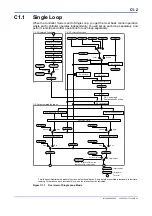
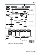
C1.2.1 Cascade Control Operation
Operating Status and Cascade Control
In cascade control mode, run/stop selection (RUN/STP) or automatic/manual/cascade
selection (A/M/C) is specified using parameters of the secondary loop (loop 2 or 4).
With “Stop” specified, the secondary loop outputs the preset output (n.POUT) and the
preset cooling output (n.POUT.C) (for heating/cooling control), and the control output
(HOUT) from the primary loop is set to its preset output (n.POUT).
With “Run” and “Cascade” specified, the control output (HOUT) from the primary loop is
converted to the PV range and used as the control set point (CSP) for the secondary
loop.
With “Run” and “Automatic” specified, one of the set points (n.SP) of the secondary loop
is selected by the SP-related functions and used as the control set point (CSP) for the
secondary loop. In this mode, the control output (HOUT) of the primary loop is the
converted value of the control set point (CSP) of the secondary loop, which is scaled to
the output range.
With “Run” and “Manual” specified, the secondary loop outputs Manual Output (MOUT)
and Manual Cooling Output (MOUTC) (for heating/cooling control). In this mode, the
control output (HOUT) of the primary loop is the converted value of the control set point
(CSP) of the secondary loop, which is scaled to the output range.
Note: “n.” in the parameter symbol denotes a PID number, which is an integer ranging from 1 to 4.
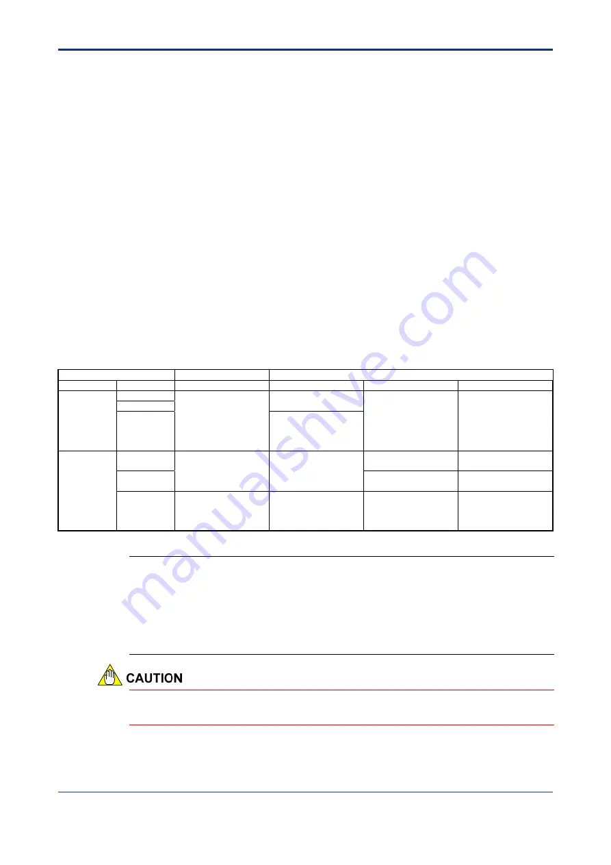
Table C1.5 Control Set Point and Control Output in Various Operating Status
Operating Status
Primary Loop
Secondary Loop
RUN/STP
A/M/C
Control Output
Control Set Point
Control Output
Cooling Control Output
Stop
Automatic
Preset output of the
primary loop
Control set point of
secondary loop
Preset output of the
secondary loop
Preset cooling output
of the secondary loop
Manual
Cascade
Range-converted
value of the control
output of the primary
loop
Run
Automatic
Range-converted
value of the control set
point of the secondary
loop
Control set point as
defined for the
secondary loop
Value computed for
the control set point
Value computed for
the control set point
Manual
Manual output of the
secondary loop
Manual cooling output
of the secondary loop
Cascade
Value computed for
the control set point of
the primary loop
Range-converted
value of the control
output from the
primary loop
Value computed for
the control set point
Value computed for
the control set point
TIP
In cascade control mode, the SP-related functions of the secondary loop converts the control output
from the primary loop expressed as a percentage into the control set point, scaled to the input range
(PRL to PRH) for the secondary loop.
- The primary loop output within the range 0.0%-100.0% is converted to the input range (PRL to PRH)
for the secondary loop.
Example: If the input range of the secondary loop is 0.0-1200.0
C, a control output of 55.0% from
the primary loop converts to a control set point of 660.0
C for the secondary loop.
If a burnout is detected in the primary loop in cascade control mode, the module
automatically switches to Automatic mode.
Summary of Contents for F3CU04-0S
Page 2: ...Blank Page...
Page 18: ...Blank Page...
Page 32: ...Blank Page...
Page 34: ...Blank Page...
Page 50: ...Blank Page...
Page 90: ...Blank Page...
Page 118: ...Blank Page...
Page 130: ...Blank Page...
Page 204: ...Blank Page...
Page 222: ...Blank Page...
Page 224: ...Blank Page...
Page 228: ...Blank Page...
Page 230: ...Blank Page...
Page 232: ...Blank Page...
Page 234: ...Blank Page...
Page 240: ...Blank Page...
Page 242: ...Blank Page...
Page 254: ...Blank Page...
Page 258: ...Blank Page...
Page 260: ...Blank Page...


