background image

12-11

IM 701510-01E

Saving and Loading Data from a Flopply Disk

12

12.5 Saving Screen Image Data

1.

Press the 

SHIFT + COPY (MENU) key 

to display the hard copy

setting menu.

2.

Press the “

FILE...

” soft key to display the image setting menu.

CENTR

” menu is also provided with DL1520/DL1520L with suffix

code -C3.

Turning ON/OFF the auto naming function
3.

Press the “

AutoFile

” soft key to select “

ON

” or “

OFF

”. For more

details concerning this function, refer to the explanation later on.

Saving screen image data
4.

Press the “

Format

” soft key to display the image data setting menu.

5.

Press the soft key corresponding to the desired format. In case you
selected “

HPGL

” or “

PS

”, continue with step 6. In case you selected

TIFF

” or “

BMP

”, continue with step 19.

6.

Press the “

Setup

” soft key to display the output setting menu.

Selecting the paper size
7.

After having selected the “

Paper Size

” setting using the rotary knob,

press the the 

SELECT key 

to select the desired paper size. In case

you selected “

PS

” at step 5, there is no need to use the rotary knob

and you may continue with step 18.

Selecting the pen speed
8.

After having selected the “

Pen Speed

” setting using the rotary knob,

press the the 

SELECT key 

to select from “

NORMAL

” or “

SLOW

”.

Selecting the XY Mode
9.

After having selected the “

XY Mode

” setting using the rotary knob,

press the the 

SELECT key 

to select from “

DOT

” or “

LINE

”.

Assigning pens
10.

After having selected the “

Pen Mode

” setting using the rotary knob,

press the the 

SELECT key 

to select from “

AUTO

” or “

MANUAL

”.

In case you selected “

MANUAL

”, continue with step 14.

11.

After having selected “

AUTO

”, and after having selected the “

Auto

Pen

” setting using the rotary knob, press the 

SELECT key 

to display

the setting frame.

12.

Use the rotary knob to set the number of pens. Press the 

RESET key

to return the default value.

13.

Press the 

SELECT key 

or the 

ESC key 

to close the setting frame.

Continue with step 18.

14.

After having selected “

MANUAL

”, use the rotary knob and the

SELECT key 

to select the “

Grid Pen

” setting, the “

TRACE1 Pen -

TRACE4 Pen

 (for DL1520/DL1520L, 

TRACE1/TRACE2/MATH

)”

setting and the “

LOAD1 Pen - LOAD4 Pen

 (for DL1520/DL1520L,

LOAD1/LOAD2

) ” setting.

15.

Use the rotary knob to set the pen numbers. Press the 

RESET key

 to

return the default value.

16.

Press the 

SELECT key 

or the 

ESC key 

to close the setting frame.

17.

Repeat steps 14 to 16 to set other items of the “

MANUAL

” setting.

18.

Press the 

ESC key 

to close the setting menu.

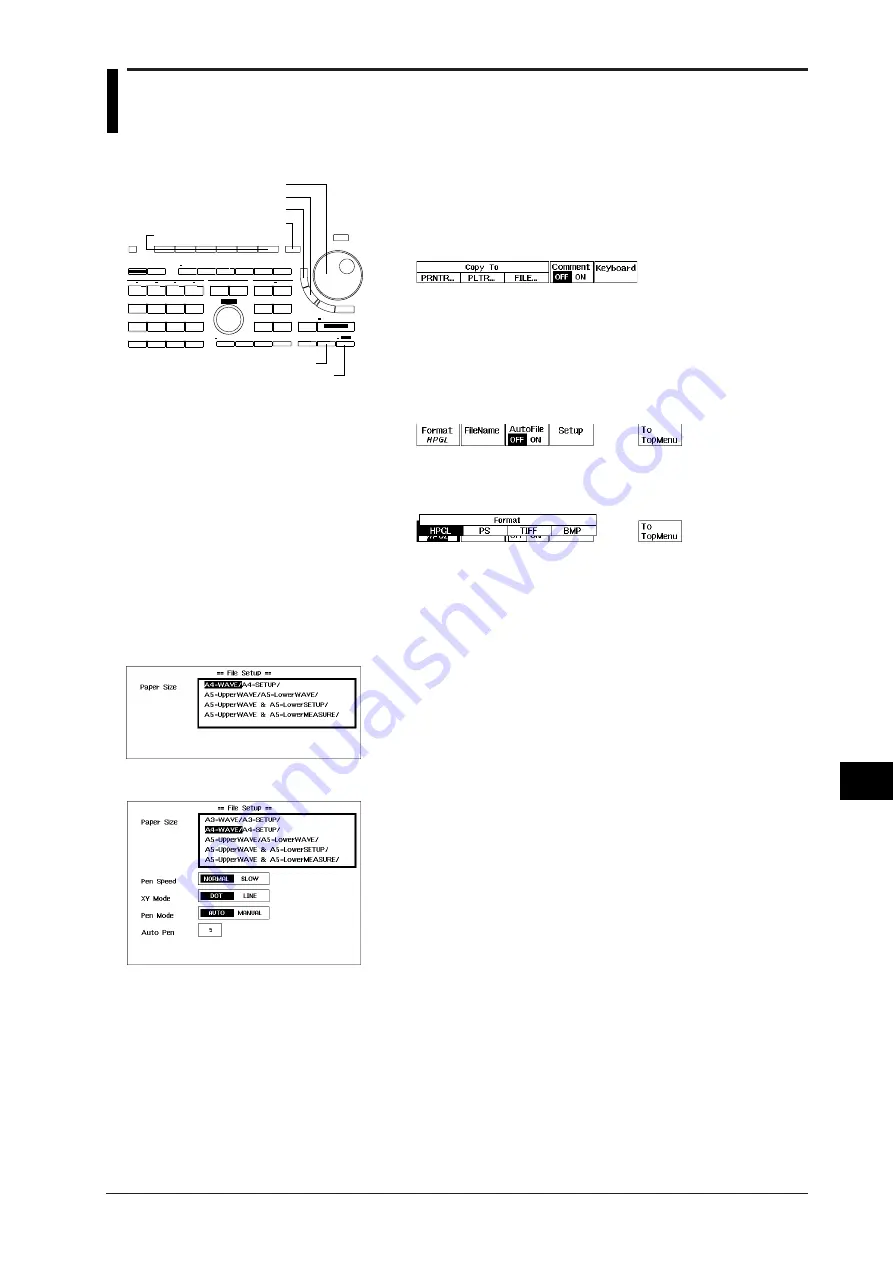
Keys and Procedure

COPY(MENU) key

Rotary knob

ESC key

SHIFT key

Soft keys

SELECT key

RESET key

Output setting menu in case "PS" is selected

Output setting menu in case "HPGL" is 
selected

Summary of Contents for DL 1520

Page 1: ...Yokogawa Electric Corporation IM 701510 01E 7th Edition Digital Oscilloscope...

Page 2: ...ion Guide DL 1540 1540L 1520 1520L IM701510 11E Describes the communications functions Communication Interface for the GP IB RS 232 C interface User s Manual Notes The contents of this manual are subj...

Page 3: ...imum Rated Voltage 125 V Maximum Rated Current 7 A F VDE Standard Power Cord Part No A1009WD Maximum Rated Voltage 250 V Maximum Rated Current 10 A Q BS Standard Power Cord Part No A1054WD Maximum Rat...

Page 4: ...49EF 150MHz probe 10 1 1 1 selectable x2 2 700998 UL CSA standard A1006WD VDE standard A1009WD BS standard A1054WD SAA standard A1024WD D F R x1 x1 x1 Rubber feet x4 A9088ZMx2 Soft case B9918EZ Q Fron...

Page 5: ...ure that all the items that you ordered have been supplied and that they are undamaged If you have any questions regarding optional spare parts or if you wish to place an order contact the dealer from...

Page 6: ...this instrument may be impaired Also YOKOGAWA Electric Corporation assumes no liability for the customer s failure to comply with these requirements The following symbols are used on this instrument T...

Page 7: ...be defective Fuse To prevent a fire make sure to use fuses with specified standard current voltage type Before replacing the fuses turn off the power and disconnect the power source Do not use a diff...

Page 8: ...polation accumulation X Y display and graticule 8 Analyzing Waveforms Describes how to measure waveforms using cursors perform automatic measurement of waveform parameters and waveform math and how to...

Page 9: ...served to prevent the danger of serious injury or death to the user Describes precautions that should be observed to prevent the danger of minor or moderate injury to the user or the damage to the pro...

Page 10: ...Interpolation 1 15 Accumulated Waveform Display X Y Waveform Display 1 16 Other Display Settings 1 17 1 5 Analyzing the Waveform 1 18 Cursor Measurements Automated Measurements Linear Scaling 1 18 Wa...

Page 11: ...Window Trigger 6 4 6 4 Setting the TV Trigger 6 5 6 5 Setting the OR Trigger Optional for DL1540 DL1540L 6 7 6 6 Setting the Pattern Trigger Optional for DL1540 DL1540L 6 8 6 7 Setting the Width Trig...

Page 12: ...10 3 10 3 Real Time Printing using the Optional Built in Printer 10 6 10 4 Connecting an External Plotter 10 7 10 5 Printing Displayed Waveforms and Additional Information using an External Plotter 10...

Page 13: ...1 Input Section 16 1 16 2 Trigger Section 16 2 16 3 Time Axis 16 3 16 4 Display 16 3 16 5 Functions 16 4 16 6 Rear Panel Input Output Section 16 5 16 7 Communication Interface 16 6 16 8 Built in Print...

Page 14: ...ending on the model Refer to the their individual specifications GP IB connector Used to connect an external plotter Connection method Page 10 7 For a description of communications functions refer to...

Page 15: ...d to set values move the cursor and select the desired items key Used to shift from one digit to the next of the value you are setting using the rotary knob SHIFT key Used to operate functions written...

Page 16: ...V DIV POSITION INPUT TRIG D REMOTE STORE RECALL CAL DISPLAY GO NO GO SOURCE COUPLING LEVEL CH 1 CH 2 CH 3 CH 4 COPY LOCAL CURSOR FILTER MISC MEASURE MATH HOLD OFF POSITION INITIALIZE ZOOM MODE POSITI...

Page 17: ...O SOURCE COUPLING LEVEL CH 1 CH 2 CH 3 CH 4 COPY LOCAL CURSOR FILTER MISC MEASURE MATH HOLD OFF POSITION INITIALIZE ZOOM MODE POSITION TYPE SNAP SHOT HISTORY CLEAR TRACE DELAY FILE 7 8 9 4 5 6 1 3 2 0...

Page 18: ...axis setting Page 5 10 Sample rate App 2 App 3 In case of the repetitive sampling mode REP is added Acquisition mode Page 7 1 NORM Normal mode ENV Envelope mode AVG Averaging mode Trigger position Da...

Page 19: ...ansion zoom box Pre zoom waveform Recalled Waveform Refer to page 11 1 Recall menu For DL1520 DL1520L LOAD3 and LOAD4 are not displayed Destination selection menu Input signal waveform Recalled wavefo...

Page 20: ...art number to quote when placing an order General Handling Precautions Never place anything on top of the instrument Never place another instrument or any objects containing water on top of the instru...

Page 21: ...der recording of the printer and accurate measurement Well ventilated location Vent holes are situated on the left side of the instrument In addition vent holes for the cooling fan are also situated i...

Page 22: ...the media used on the SCSI device is formatted with another equipment such as a PC or the pin configuration of the connector is different Refer to section 16 7 for the SCSI specification Also for info...

Page 23: ...l equipment being connected beforehand 2 Turn the power switches OFF on all equipment that are being connected Connecting DL1520L and the SCSI device 3 Connect one end of the SCSI cable to the connect...

Page 24: ...feature will be negated Connecting the Power Cord 1 Make sure that the main power switch is OFF 2 Plug the power cord into the power connector socket on the rear panel of the instrument 3 Plug the oth...

Page 25: ...he power is turned ON or if the normal waveform display screen does not appear check the following points Check that the power cord is plugged in properly Check that the correct voltage is being suppl...

Page 26: ...ter calibration Item Specifications Conditions Setting 10 1 Setting 1 1 Input impedance capacitance 10 M 2 approx 14 pF 1 M 1 5 approx 100 pF When used with this instrument Attenuation ratio 10 1 2 5...

Page 27: ...ole Explanation Reason for probe compensation If the probe s input capacitance is outside the specified range the gain will not be constant across different frequencies preventing display of the corre...

Page 28: ...are set 8 Turn the rotary knob to select SET and press the SELECT key to confirm the settings 9 Press the ESC key to close the menu Explanation Setting the Date Time ON or OFF When you set the mode t...

Page 29: ...n the following cases When remote state is active i e the REMOTE indicator is lit When a short or long copy is being output to the built in printer When the floppy disk is being accessed e g when data...

Page 30: ...1 CH2 for DL1520 DL1520L Depending on whether input is applied or not the channels are automatically turned ON or OFF In case of an amplitude of at least approx 50 mV and probe attenuation is 1 1 the...

Page 31: ...n unchanged DISPLAY FORM Settings related to graticule scale marker and Waveform information remain unchanged Auto set up settings related to waveform analysis MEASURE Settings related to automated me...

Page 32: ...waveform display frame DELAY Delay time 0 s HOLD OFF Mode OFF Hold off time MIN 0 2 s Default settings related to other settings ACQUISITION Mode NORMAL LENGTH for DL1520L DL1540L Record length 10K FI...

Page 33: ...ms only you can either turn off the input signal by pressing the CH key or move the vertical position of the displayed channel Snapshot waveforms will remain on the screen even if calibration is perfo...

Page 34: ...ameters are calibrated Ground level offset A D converter gain Trigger threshold level Time axis for equivalent time sampling Calibration takes approximately five seconds No keys are operative during c...

Page 35: ...the rotary knob 2 When the new value has been selected using the rotary knob use the keys to move to the next position to be changed Ex Explanation Entry using the keyboard The operation described in...

Page 36: ...entry of a comment refer to 10 6 Entering a Comment page 10 10 Function keys on the soft keyboard DEL Deletes the character or symbol left of the cursor in the character string INS Switches between in...

Page 37: ...turn the display of the recalled waveform off press the CH key corresponding to the number of the recalled waveform displayed as MEM and select OFF at the appeared menu Refer to page 11 2 step 13 and...

Page 38: ...elow Note that low frequency signals and low frequency contents are not acquired if AC is selected 0 dB 3 dB 150 MHz Attenuation 0 dB 3 dB 150 MHz Attenuation less than 10 Hz when using 1 1 probe less...

Page 39: ...set voltage will remain unchanged even if the input coupling is later switched to DC When the probe attenuation is changed the offset voltage also changes accordingly The offset voltage remains unchan...

Page 40: ...ft key corresponding to the desired attenuation Explanation Probe attenuation Probe attenuation can be selected from 1 1 10 1 100 1 and 1000 1 The default is 10 1 Set to 10 1 when using the probe supp...

Page 41: ...another Each time the soft key is pressed ON or OFF are displayed alternately and the waveform will be inverted accordingly Indication of an inverted signal When a waveform is inverted the correspond...

Page 42: ...e set in multiples of 1 2 and 5 e g 1 V div 2 V div 5 V div Variable mode When Variable is highlighted V div can be set in fine steps as shown below CAL Setting value Variable Setting range Setting st...

Page 43: ...rms which cannot be moved Snapshot waveforms Indication of the vertical position For an input signal waveform or computed waveform the corresponding trace No and ground level mark are displayed on the...

Page 44: ...m Specifications Connector type BNC Maximum input voltage 250 V DC ACpeak or 177 Vrms when the frequency is 1 kHz or below CAT I and II Input band DC to 100 MHz Fequency range of external 40 Hz to 80...

Page 45: ...must be continuous No burst signal is allowed If the frequency of the clock signal is out of specification a warning message External Clock too slow or External Clock too fast will be displayed at the...

Page 46: ...Real time repetitive 2 Update mode 50 ns to 5 ns div Repetitive Update mode If maximum displayable record length is set to 400 K available only if trigger mode is single DL1520L DL1540L Time axis sett...

Page 47: ...pective of the displayed menu since a T div setting knob is available But for DL1520L DL1540L note that it is not possible to select a short time axis 50ns div or less if maximum displayable record le...

Page 48: ...per side of the screen and will show which part of the waveform is shown on the screen Other modes than roll mode Horizontal position is 0 div Horizontal position is moved to 4 div Horizontal position...

Page 49: ...tate level page 6 10 page 6 8 page 6 7 page 6 5 page 6 4 page 6 2 Selection of trigger source slope Trigger level Selects trigger condition Center level Width Selection of broadcasting type Selection...

Page 50: ...onding to the desired attenuation ratio 11 Turn the rotary knob to select the desired trigger level for the external trigger Explanation Types of Trigger sources and setting the trigger slope level CH...

Page 51: ...ge will be multiplied by10 100 and 1000 respectively EXT range is 1 V 1 V to 1 V in steps of 4 mV EXT range is 10 V 10 V to 10 V in steps of 40 mV For DL1540 DL1540L refer to EXT external Trigger on t...

Page 52: ...ected from the following types IN Trigger will be activated when the trigger source level enters a preset voltage range OUT Trigger will be activated when the trigger source level exits from a preset...

Page 53: ...nu will be displayed next to the trigger type selection menu 5 Press the Field soft key to select the desired field number 6 Turn the rotary knob to select the desired line number Selecting the polari...

Page 54: ...1 2H Field 1 Field 2 Line No 2245 2250 1126 1127 1128 1129 1130 1131 1132 1166 2251 Line No 1682 1687 1688 1169 1170 1171 1172 1173 1174 1728 Line Nos in cannot be set Selecting the polarity Polarity...

Page 55: ...pe state and level CH1 CH2 CH3 CH4 Selects which of the input signals CH1 to CH4 will be used as the trigger source Select the trigger slope state from the following Activates a trigger when the trigg...

Page 56: ...kip to step 7 Activating a trigger in synchronization with the clock signal 4 Continuing from step 3 select the desired clock channel and press the corresponding soft key 5 Select the trigger slope of...

Page 57: ...xample CH1 H CH2 L CH3 X CH4 X Condition ENTER Activating a trigger in synchronization with the clock signal Select the trigger condition from the following TRUE Activates a trigger on the slope edge...

Page 58: ...ft key corresponding to the channel to be used as a trigger source and set the trigger state 7 Turn the rotary knob to set the desired trigger level Explanation Selecting the width condition PULSE T T...

Page 59: ...source state and setting the trigger level The trigger source should be selected from CH1 to CH4 Select the trigger state from the following H The trigger source level is above the preset trigger lev...

Page 60: ...Auto mode operations are carried out even if auto level mode has been selected for a trigger other than an edge trigger Furthermore roll mode will be activated irrespective of the trigger type if T d...

Page 61: ...used in real time sampling mode For setting the number of repetitions refer to page 7 7 Points to note when setting the trigger mode If single short mode or single mode is selected with a T div setti...

Page 62: ...the action on trigger The action can be selected from the following PRINTER Outputs hardcopy to the built in printer FD P P Saves all the displayed waveforms as P P compressed data on a floppy disk w...

Page 63: ...atically to the single short mode or single mode Even after canceling the action on trigger the previous trigger mode will not be restored When the action on trigger is restarted EXEC after first bein...

Page 64: ...al is used as the trigger source without any processing The trigger level becomes the center of the amplitude of the trigger source The default value is AC The trigger coupling setting applies to all...

Page 65: ...ROM version the trigger position can be set with in steps of 1 50 div using the rotary knob Setting the trigger delay and trigger position The trigger position indicates which position of the wavefor...

Page 66: ...the duration between the point at which a trigger is activated and the point at which data acquisition starts Delay time Trigger point T Trigger position The setting range is 0 to 9 999 s The setting...

Page 67: ...rned OFF Turning the hold off function ON OFF The hold off time which has been set will be retained even if the hold off function is set to OFF If the hold off function is switched ON again the hold o...

Page 68: ...press the Length soft key The screen returns the length selection menu For DL1520L 2M menu is not displayed 3 Press the soft key corresponding to the maximum displayable record length that you want t...

Page 69: ...Selection of 400 KW 1 MW and 2 MW record lengths is available only if trigger mode is single For DL1540L it is not possible to switch on Channel 3 or Channel 4 while record length is set to 2 MW It is...

Page 70: ...lied is shown below When FULL is selected the frequency bandwidth is 150 MHz 3 dB 20 MHz FULL 150 MHz Smoothing process A moving average value is obtained for each five points of sampling data and the...

Page 71: ...3 and 4 Explanation Expansion Rate Expansion rate limits The expansion rate which can be set varies according to the specified record length of the pre zoom waveform The specified record length depen...

Page 72: ...ype when displaying an X Y waveform The type of display depends on the settings in the expansion menu For X Y mode refer to page 7 13 ZOOM mode X Y Mode OFF X Y T Y X Y OFF V T pre zoom X Y pre zoom V...

Page 73: ...form and its expanded waveform are displayed at the same time If you press the ZOOM Mode soft key while accumulated waveform display is in progress accumulated waveform display will be reset If you pr...

Page 74: ...d number of acquisitions 4 If no trigger has been activated already press the START STOP key or once more the N SGL soft key to start data acquisition Displaying a specific acquired data by selecting...

Page 75: ...data Display Trace The way of displaying the acquired data can be selected from the following Displaying the selected waveform only Selecting the waveform can be done by setting the Display Number or...

Page 76: ...b to set the number of the data you want to see display number The corresponding waveform will appear on the screen Displaying a specific acquired data by selecting its time of acquisition 5 Continuin...

Page 77: ...tory memory function Data will not be acquired in case of the repetitive sampling mode If data acquisition is aborted while in progress only the waveforms which have been acquired so far will appear o...

Page 78: ...interpolation Displays the sampling data as a horizontal line LINE Interpolates between two dots with a straight line SINE Generates interpolation data using a sine function and interpolates between...

Page 79: ...accumulated waveforms except the most recent one Points to note The following operations apply only to the latest waveform s data if they are performed using accumulated waveform display Cursor measu...

Page 80: ...ected from the following three types OFF Displays only the V T waveform X Y Displays only the X Y waveform In case the zoom setting has been set to ZOOM the display will show the expanded waveform as...

Page 81: ...ss the Scale soft key and select ON or OFF Turning the Marker ON OFF 2 After step 1 has been completed press the Marker soft key and select ON or OFF Explanation Graticule The graticule type can be se...

Page 82: ...0L CH3 and CH4 are not displayed Voltage axis sensitivity Channel No Probe attenuation Input coupling Points to note concerning the waveform information display If a recalled waveform is displayed the...

Page 83: ...3 and 4 to adjust the intensity of other items Explanation Intensity Intensity can be set to one of 15 levels with the darkest intensity 1 and the brightest intensity 15 Items for which the intensity...

Page 84: ...AD1 LOAD2 and ALL are displayed instead of the trace selection menu shown below 7 After having pressed any of the T1 T2 or T1 T2 soft keys use the rotary knob to adjust the position of the cursor Meas...

Page 85: ...d Using vertical cursors to measure time difference frequency voltage voltage difference V T In all cases excluding ALL T1 Time difference between position of cursor T1 and trigger position T2 Time di...

Page 86: ...frame One time position is used for the P P value of the displayed waveform and two points maximum and minimum are measured at this position The default setting 2 50 div for T1 2 50 div for T2 Horizo...

Page 87: ...ible will be displayed Cursor measurement is also possible for expanded waveforms When switching the display to show the expanded waveform the position of the cursor on the screen does not change When...

Page 88: ...completed press the dX soft key to display the cursor setting menu The vertical cursors will appear on the screen 6 After having pressed any of the T1 T2 or T1 T2 soft keys use the rotary knob to adj...

Page 89: ...fference of the Y axis dY DY V2 V1 where V1 is the voltage at the Y axis where cursor H1 intersects and V2 is the voltage at the Y axis where cursor H2 intersects Cursor movement method The cursors ca...

Page 90: ...ent values You must first stop waveform acquisition then you can execute the measurement by pressing the ALL Scan EXEC soft key Each press of the key takes a single measurement of the various waveform...

Page 91: ...n selected the mark becomes Use the rotary knob to first highlight an item and then de select it Switches between menus For DL1520 DL1520L another menu is displayed Setting the distal proximal values...

Page 92: ...ay the value setting box 24 Use the rotary knob to set the desired value Press the RESET key to restore the new value to the default value 25 Press the SELECT key or the ESC key to close the value set...

Page 93: ...DL1520 DL1520L or DL1540L 1 Set the measurement range measurement items distal proximal values and channel delay to appropriate values Then confirm that the Measure soft key in the automated measureme...

Page 94: ...easuring items such as rise time and fall time High represents the voltage for the most frequently occurring high amplitude at 100 level while Low represents the voltage for the most frequently occurr...

Page 95: ...ferent menu is selected However the cursors cannot then be moved Values gathered by the automated measurement function will be cleared if the cursor measurement function is turned ON However pressing...

Page 96: ...aveform will be displayed In case delay measurement is set ON the maximum number of displayed measurement items becomes 11 In case of three or four waveforms under measurement Up to 6 measurement valu...

Page 97: ...g function it is necessary to select the waveform of measurement to set the coefficient A and the offset value B and to apply a unit Selecting the waveform of measurement 5 Use the rotary knob to sele...

Page 98: ...waveforms Returning to the top menu 14 Press the ESC key to close the linear scaling setting menu 15 Press the To Topmenu soft key to return to the MISC menu Explanation Waveforms which cannot be meas...

Page 99: ...ng types can be selected The default value is OFF OFF computation will not be carried out 1 2 3 The result of adding waveform data of CH1 and CH2 will be displayed as trace 3 or MATH 1 2 3 The result...

Page 100: ...ta When this data is stored or saved on the internal memory floppy disk SCSI device information indicating that this is a computed waveform and the voltage axis information after the computation are n...

Page 101: ...transient signals which attenuate completely within the time window HANNING Useful for signals which are continuous and not periodical FFT frequency band Maximum 50 MHz Display format The display form...

Page 102: ...ht edge 5 00 div of the waveform display frame However there is no data at the 501 position of the rigth edge Thus when you move the cursor to this position the display will show The default setting i...

Page 103: ...ing the determination function refer to page 9 5 Note The determination waveforms are saved in the internal memory Old determination waveforms which are already present in the internal memory will be...

Page 104: ...rt of the waveform 10 After having completed step 6 or step 9 press the PART soft key to display the editing menu 11 After having pressed the T Range soft key select either T1 or T2 to set either boud...

Page 105: ...en when new ones will be saved An error message will not appear Therefore verify before saving whether or not determination waveforms already exist in the internal memory Refer to steps 18 to 20 17 Re...

Page 106: ...g on the condition setup menu press the SELECT key to select the desired sequence The following types can be selected SINGLE Stops determination when a NO GO determination is made CONTINUE Carries out...

Page 107: ...etermination function 33 Press the EXEC soft key The name of the soft key will change to ABORT Judgement results per trace GO X NO GO Not under measurement Number of times GO NO GO judgement is perfor...

Page 108: ...haracters before the assigned file number for instance NOGO0000 The entered file name is will be reset when the action becomes NONE or when GO NOGO determination is set to OFF The file name will be re...

Page 109: ...The following operations are not possible after having pressed the EXEC soft key In order to perform these operations it is necessary to set Mode at the GO NO GO top menu to OFF after having pressed t...

Page 110: ...s such as parameter setup determination logic sequence determination and action after determination refer to page 9 9 9 10 Executing aborting determination after setting selecting the parameters refer...

Page 111: ...g using the rotary knob press the SHIFT MISC KEYBOARD key to display the keyboard 13 Use the keyboard to enter the desired value For details concerning operation of the keyboard refer to page 4 7 14 A...

Page 112: ...ter having selected either NONE or PRINT continue with step 21 20 Use the keyboard to enter the name of the file The entered filename will be displayed at the FileName setting For details how to opera...

Page 113: ...iv 0 04 div Overshoot Overshoot 0 to 200 1 Duty Duty 0 to 100 1 Freq 0 02 to 10 div Period Rise Fall Width Width 0 to 10 div 0 01 div Delay Delay 10 to 10 div 0 01 div INTEG1TY INTEG2TY 3 4x1038 INTEG...

Page 114: ...ermination The following operations are not possible after having pressed the EXEC soft key In order to perform these operations it is necessary to set Mode at the GO NO GO top menu to OFF after havin...

Page 115: ...ation is made Signal output circuit diagram 51 LS06 2 2 k 5 V 5 V Output Connector 1 25 26 50 2 27 3 28 24 49 23 48 Pin configuration Pin No Pin No 1 2 26 27 Signal name NO GO OUT GND GO OUT GND OPTIO...

Page 116: ...nect to another instrument or when you touch the NO GO OUT terminal CAUTION Never apply an external voltage to the NO GO OUT and GO OUT terminals otherwise damage to the instrument may result When con...

Page 117: ...l chart is left in contact with plastic films containing plasticizer for instance vinyl chloride film cellophane tape etc for a long period of time discoloration will occur on the recording area of th...

Page 118: ...so that the chart protrudes approximately 10 cm from above the guides The paper can be inserted easily after cutting off both corners of the end of the paper Rotate the chart to make sure that it is p...

Page 119: ...ded waveform 6 Press the Range soft key to display the printing range setting menu 7 After having pressed either the T1 or T2 soft keys use the rotary knob to adjust the position of the cursor You can...

Page 120: ...information setup and waveform parameters can also be output To output the hardcopy only select OFF Setup Information Measurement Values of Waveform Parameters Setting the printing type SHORT short c...

Page 121: ...the printing range Setting the expansion rate For setting limits and expansion rate refer to page x x This setting is not necessary if expanded waveforms have already been displayed before the hardco...

Page 122: ...e Before carrying out real time printing verify the following settings The trigger mode should be set to Auto mode or Auto Level mode The history memory function should be set to OFF The time base sho...

Page 123: ...tter will switch this instrument to talk only mode automatically Plotter Set the plotter to listen only mode Note For a description of the GP IB interface refer to the Communication Interface User s M...

Page 124: ...SELECT key to select from AUTO or MANUAL In case of AUTO 8 After having selected AUTO and after having selected the Auto Pen setting using the rotary knob press the SELECT key to display the setting...

Page 125: ...Mode The pens can be assigned according to the following two methods AUTO Assigns pens automatically as shown in the table below according to the number of pens Number of GRID TRACE LOAD installed pen...

Page 126: ...ents will not be displayed Explanation Number of characters which can be entered Up to 25 characters may be entered Displaying a comment The comment will appear above the waveform display frame as sho...

Page 127: ...to DL1520 DL1520L using the printer connecting cable of standard accessories With some printers the screen image cannot be printed properly If this problem continues to occur even when the printer ha...

Page 128: ...ot printed for DL1520 with software ROM version before 1 30 LIPS Printed by Canon LASER SHOT A404F PR201 Printed by Canon LASER SHOT A404F PR201 emulation PCL5 Printed by HEWLETT PACKARD Laser Jet 5L...

Page 129: ...ress the EXEC soft key to execute waveform storing Recalling a waveform 3 After step 2 has been completed press the RECALL soft key to display the waveform recalling menu 4 Press the Source soft key t...

Page 130: ...ll be displayed at the 0div location on the voltage axis Moving waveforms You can move the position of input signal waveforms and recalled waveforms seperately When displaying recalled waveforms press...

Page 131: ...ey to display the recall memory selection menu 5 Press the soft key corresponding to the memory No from which the setting parameters are to be recalled 6 Press the EXEC soft key to execute recalling E...

Page 132: ...abel facing up and the shuttered side facing towards the drive then insert it into the floppy drive Insert it until the eject button pops up Removing the floppy disk from the drive Make sure that the...

Page 133: ...matting the floppy disk The following four MS DOS format types are available 2DD 640K Formats a 2DD floppy disk with 8 sectors to hold 640 KB 2DD 720K Formats a 2DD floppy disk with 9 sectors to hold...

Page 134: ...form data as well as HP GL PS Postscript TIFF and BMP screen image data Floppy disks formatted in a format other than those specified on the previous page cannot be used If an error message appears wh...

Page 135: ...ft key corresponding to the waveform to be saved For DL1520 DL1520L menus such as TRACE1 TRACE2 MATH and ALL are displayed instead of the source wave setting menu shown below 7 Press the FileName soft...

Page 136: ...ress the ACQ soft key to display the save load setting menu and a list of files 4 Press the SAVE soft key to display the saving menu 5 Press the Type soft key to display the saving format menu 6 Selec...

Page 137: ...necessary repeating the same filename at Step 5 Moving loaded ACQ waveforms 14 The way to move these waveforms is exactly the same as for input signal waveforms For details refer to page 5 7 Canceling...

Page 138: ...eforms displayed as trace About the saved data For a description of the format of the data to be saved refer to Appendix 5 Output Data Format used When Saving Waveform Data App 12 Data is saved in the...

Page 139: ...isplay frame is saved Thus if the saved waveform exceeds this range vertically the part exceeding this range will not be displayed if the waveform is subsequently loaded and scrolled vertically For DL...

Page 140: ...setting parameters 3 Press the SETUP soft key to display the save load setting menu and a list of files 4 Press the SAVE soft key to display the saving menu 5 Press the FileName soft key to display t...

Page 141: ...pproximately 4 K bytes extra are required for each zone waveform Checking the free space on a floppy disk Refer to page 12 3 for a description of this procedure Entering a file name The following poin...

Page 142: ...NORMAL or SLOW Selecting the XY Mode 9 After having selected the XY Mode setting using the rotary knob press the the SELECT key to select from DOT or LINE Assigning pens 10 After having selected the P...

Page 143: ...tup settings are necessary for printing out image data from a PC or such to a plotter The contents of printing paper size printing size and printing location depend on the format of the data and can b...

Page 144: ...ing a file name A file name must always be specified Up to eight characters can be entered All the characters on the keyboard can be used However the following file names cannot be used due to MS DOS...

Page 145: ...added before the file name of the protected file Canceling protection 7 After step 4 has been performed use the rotary knob to select the file at the beginning of which a symbol is added 8 Press the...

Page 146: ...rformed if the floppy disk is write protected An error message will appear if an attempt is made to protect or delete files It is not possible to delete more than one file at once This protection sett...

Page 147: ...media selection menu 3 Press the SCSI soft key to select the SCSI device as the media Explanation Selecting the Media Select from the following Floppy Floppy disk SCSI SCSI device Refer to Section 16...

Page 148: ...n menu 3 Press the Format soft key to display the format selection menu Formatting 4 After having selected OK using the rotary knob press SELECT key When formatting is complete the message Formatting...

Page 149: ...f Image data files Points to note concerning formatting The following three directories are created automatically when a medium is formatted using this instrument DL_WAVE Directory for BIN binary wave...

Page 150: ...ting menu 6 Press the soft key corresponding to the waveform to be saved 7 Press the FileName soft key to display the keyboard 8 Use the keyboard to enter the filename For details regarding the usage...

Page 151: ...splaying the loaded waveform Saving ACQ waveform data 3 Press the ACQ soft key to display the save load setting menu and a list of files 4 Press the SAVE soft key to display the saving menu 5 Press th...

Page 152: ...peat Steps 11 to 13 as necessary selecting the same filename at Step 12 Moving loaded ACQ waveforms 14 The way to move these waveforms is exactly the same as for input signal waveforms For details ref...

Page 153: ...data type the waveforms to be saved are the input signal waveforms displayed as trace About the saved data For a description of the format of the data to be saved refer to Appendix 5 Output Data Form...

Page 154: ...result in overwriting the old files Points to note when saving loading waveform data Acquisition stops when saving or loading is started Only waveform data located within 5 12 div of the center of th...

Page 155: ...splay the save load setting menu and a list of files 4 Press the SAVE soft key to display the saving menu 5 Press the FileName soft key to display the keyboard 6 Use the keyboard to enter the filename...

Page 156: ...f GO NO GO zone waveforms are included approximately 4 K bytes extra are required for each zone waveform Checking the free space on a medium Refer to page 13 3 for a description of this procedure Ente...

Page 157: ...CT key to select from NORMAL or SLOW Selecting the XY Mode 9 After having selected the XY Mode setting using the rotary knob press the the SELECT key to select from DOT or LINE Assigning pens 10 After...

Page 158: ...Selecting the paper size These Setup settings are necessary for printing out image data from a PC or such to a plotter The contents of printing paper size printing size and printing location depend o...

Page 159: ...e The following points must be kept in mind when entering a file name A file name must always be specified Up to eight characters can be entered All the characters on the keyboard can be used However...

Page 160: ...ction 7 After step 4 has been performed use the rotary knob to select the file at the beginning of which a symbol is added 8 Press the Protect soft key and the protection will be canceled The symbol b...

Page 161: ...cting or deleting data Protection setting cannot be performed if the medium is write protected An error message will appear if an attempt is made to protect or delete files It is not possible to delet...

Page 162: ...igger is activated A trigger is activated Pre trigger Repeat interval for trigger output Trigger Trigger Post trigger Post trigger Pre trigger Acquisition Pre trigger Internal process time 2 3 1 1 Dur...

Page 163: ...ABORT Aborting the download function 8 Press the ABORT soft key The name of the soft key will change to EXEC Explanation Download setting Dataout Downloading data from this instrument should only be...

Page 164: ...front panel Explanation ROM check screen The ROM check screen as shown below enables you to check the ROM version the date the ROM was programmed the model type and whether options are installed An ex...

Page 165: ...ose the density setting frame Explanation Setting the printer density Printer Density This setting controls the printing density of hard copies on the built in printer Setting range 0 to 3 Default set...

Page 166: ...is faulty Keys do not function Instrument is in remote mode Press the LOCAL key to activate local mode Other causes Make correct trigger settings for the input signal Trigger settings are incorrect No...

Page 167: ...ned ON is incorrect Mismatch in the media format Set ID No to 5 Turn the power ON in the following order SCSI device DL1520L Format the media with the DL1520L 3 3 3 6 13 2 Data can not be saved to the...

Page 168: ...output is aborted 13 2 13 Exit from GO NO GO mode 9 5 6 10 11 14 Execution completed Error Warning Message In addition to the messages given below there are also some other error warning messages code...

Page 169: ...SINGLE N SGL as the trigger mode or with history mode 10 10 717 It is not possible to display a time stamp during acquisition 7 9 718 It is not possible to use the ALL display during acquisition 7 9 7...

Page 170: ...to set the repetitive sampling range in FFT mode 7 1 816 For DL1540 It is not possible to set history mode in SGL S SGL L N SGL as the trigger mode For DL1520L DL1540L It is not possible to set histor...

Page 171: ...ngth is 400K 1M words the trigger mode can only be set to SINGLE For DL1540L Since the record length is 400K 1M 2M words the trigger mode can only be set to SINGLE 6 13 831 For DL1520L Since the recor...

Page 172: ...when the instrument seems to be defective Contact your nearest YOKOGAWA representative and proceed according to his instructions Do not use this function unless the instrument is defective 1 Press th...

Page 173: ...power cord from the power supply 3 Pull out the fuse holder by placing a screw driver under the tab and pulling the holder forward 4 Remove the blown fuse located at the front of the fuse holder Note...

Page 174: ...and doesn t cover any other items nor expendable items items which wear out In order to use the instrument over a prolonged period of time we recommend periodic replacement Contact your nearest Yokog...

Page 175: ...DC to 20 MHz 1 mV div is available on DL1540 DL1540L 3 dB point when AC coupling used 10 Hz or below 1 Hz or below in case the accessory 10 1 probe is being used Inter channel skew 2 ns or less under...

Page 176: ...cquires waveform automatically if no trigger is activated for more than approx 100 ms Auto level Automatically sets the trigger level to the median of the amplitude if no trigger is activated for more...

Page 177: ...input voltage 6 V Input frequency range 40 Hz to 15 MHz only for continuous clock Input level TTL CMOS level recommended 0 3 Vp p or greater at the end of the connector 0 15 V or greater relative to...

Page 178: ...ultaneously Graticule Scale Allows selection of scale from frame and grid turns display of the scale ON OFF turns the marker ON OFF Intensity adjustment Intensity can be adjusted for each displayed it...

Page 179: ...vel Input pulse width 25 ns or more for both High and Low levels Trigger output Connector type BNC TRIG OUT Output level TTL for DL1540 DL1540L Output logic Negative trailing edge Output delay time 20...

Page 180: ...interface is not supported by DL1540 DL1540L Item Specifications Connector type Centronics interface connector half pitch 36 pin with a printer connecting cable to D sub socket Electrical specificatio...

Page 181: ...line dot method Dot density 6 dots mm Paper width 112 mm Real time printout max chart speed of 16 7 mm s speed drops at time axis settings slower than 500ms div 16 9 Built in Floppy Disk Drive Item S...

Page 182: ...L Channel Input terminated with 50 Standard operating conditions Ambient temperature 23 2 C Ambient humidity 55 10 RH Power voltage and frequency fluctuation Less than 1 of the rated voltage frequency...

Page 183: ...ertical using supports Battery back up Set up data and internal clock are backed up by a built in lithium battery Battery life is approx 10 years at ambient temperature of 23 C Accessories Power cord...

Page 184: ...Unit mm If not specified the tolerance is 3 However in cases of less than 10mm the tolerance is 0 3mm Rear View 213 268 8 215 278 The drawing below shows the exammple for DL1540 DL1540L The external...

Page 185: ...5 4 5 5 Page 8 13 14 2 15 7 Page 5 12 Page 6 2 6 4 6 5 6 7 6 8 6 10 Page 6 2 6 4 6 5 6 7 6 8 6 10 Page 6 12 Page 6 14 Page 6 16 Page 6 17 6 18 Page 6 19 Page 7 1 Page 7 3 Page 7 4 Page 7 9 Page 7 11...

Page 186: ...00M 500k x 2 100M 1M x 2 100M 2 5M x 2 100M 5M x 2 100M 10M x 2 100M 10M x 2 5K x 2 10K x 2 5K x 2 10K x 2 5K x 2 10K x 2 5K x 2 10K x 2 5K x 2 10K x 2 5K x 2 10K x 2 5K x 2 10K x 2 5K x 2 10K x 2 5K...

Page 187: ...value in is given the displayed record length and the record length stored in the acquisition memory are the same 2 The sample rate given in for the envelope mode is the rate at which data are acquir...

Page 188: ...ne of CH3 CH4 is ON 1 The displayed record length given in refers to the record length stored in the acquisition memory Only when the trigger mode is auto or auto level data of a record length given i...

Page 189: ...500 x 2 1K x 2 500 x 2 1K x 2 500 x 2 1K x 2 500 x 2 1K x 2 500 x 2 1K x 2 500 x 2 1K x 2 500 x 2 1K x 2 500 x 2 1K x 2 500 x 2 1K x 2 500 x 2 1K x 2 500 x 2 500 x 2 500 x 2 500 x 2 500 x 2 500 x 2 50...

Page 190: ...0M 5M x 2 100M 10M x 2 100M 10M x 2 5K x 2 10K x 2 5K x 2 10K x 2 5K x 2 10K x 2 5K x 2 10K x 2 5K x 2 10K x 2 5K x 2 10K x 2 5K x 2 10K x 2 5K x 2 10K x 2 5K x 2 10K x 2 5K x 2 10K x 2 5K x 2 5K x 2...

Page 191: ...250k x 2 100M 500k x 2 100M 1M x 2 100M 2 5M x 2 100M 5M x 2 100M 10M x 2 100M 10M x 2 50K x 2 100K x 2 50K x 2 100K x 2 50K x 2 100K x 2 50K x 2 100K x 2 50K x 2 100K x 2 50K x 2 100K x 2 50K x 2 100...

Page 192: ...KW length is not available if T div is set between 50ns and 5ns or if trigger mode is other than single Rep Repetitive sampling mode When Mode other than Envelope Mode is Active At Least One of CH3 CH...

Page 193: ...s 20 s 10 s 5 s 2 s 1 s 500ns 200ns 100ns When Maximum Displayable Record Length is set to 1MW Selection of 1MW length is not available if T div is set between 50ns and 5ns or if trigger mode is othe...

Page 194: ...available if T div is set between 50ns and 5ns if trigger mode is other than single or if CH3 or CH4 is ON Rep Repetitive sampling mode When Mode other than Envelope Mode is Active At Least One of CH...

Page 195: ...piral loop Area S S0 2 S1 Number of overlaps varies according to the number of loops Stop point S0 S1 Start point Stop point Start point S0 Waveform S1 Integ2XY 1 When only one Y data corresponds to X...

Page 196: ...ficient of Y axis conversion equation for each waveform 4 VOffset 0 00000e 00 Offset co efficient of Y axis conversion equation for each waveform 4 VDataType IS2 Type of waveform data of each waveform...

Page 197: ...data sampled at the same time 3 Maximum number of blocks per group or repetitions in the case of single N trigger mode Maximum number of blocks applies if the number of blocks varies from waveform to...

Page 198: ...ckNumber 1 DisplayPointNo 6 DisplayBlockSize 500 TriggerPointNo 250 Date 95 12 01 Time 18 17 11 SampleRate 100 MHz TraceName Ch1 Ch2 Ch3 Ch4 Unit V V V V MediaNo 1 StartBlockNo 1 StartPointNo 1 EndBlo...

Page 199: ...input 5 2 trigger 6 16 cursor 8 1 8 5 8 19 cursor measurements 1 18 D Page data list 12 15 13 15 date time setting 3 9 DC 1 2 DC coupling 5 2 default settings 4 4 delay measurement 8 9 setup 8 12 tim...

Page 200: ...1 18 8 1 parameters 8 11 menu map App 1 mode 6 12 model name 2 N Page N SGL 6 13 normal mode 1 10 6 12 7 1 NTSC 6 5 O Page offset voltage 5 2 options 2 OR trigger 6 7 output signal 14 1 P Page PAL 6...

Page 201: ...10 time stamp 7 7 7 9 timebase selection 1 4 5 8 timeout 6 10 trigger action on 1 10 6 14 coupling 1 10 6 16 delay 1 11 6 17 6 18 edge 1 8 6 2 EXT 6 3 hold off 1 11 level 1 8 6 1 LINE 6 3 mode 1 10 6...

Reviews: