background image

2.3  Connecting Devices

2.3.2  Connecting the Power Supply Connector

2-42

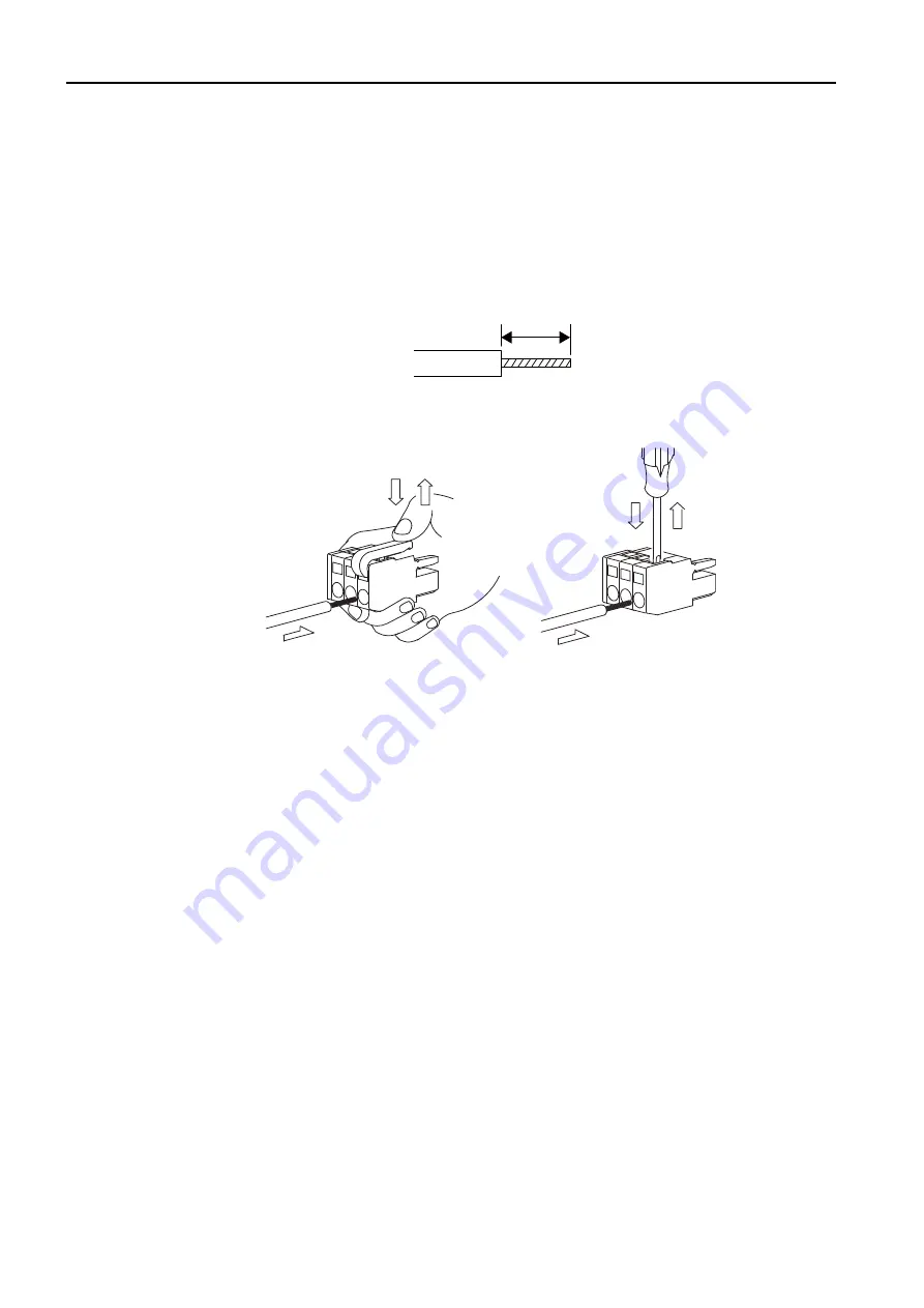
Procedure to Make a 100/200-VAC Power Cable

The power supply pins are contained in a removable connector. Use the following procedure to 
wire the power supply connector. Use a twisted-pair cable with a wire size of AWG28 to 
AWG13 (0.08 to 2.6 mm

2

) to connect the 100/200-VAC power supply to the power supply 

connector on the Controller. 

Use the following procedure to make the cable.

1.

Strip the wires.

Strip the wires for a length of 8 to 9 mm from the end to expose the conductors.

2.

Clamp the wires.

Insert the conductors into the back of the plug and clamp them securely.

8 to 9 mm

Summary of Contents for MP3000 Series

Page 1: ...MP3000 Series SETUP MANUAL MANUAL NO SIEP C880725 00D 1 2 3 4 5 6 System Configuration Installation and Connections Machine Controller Setup Creating User Programs Debugging Programs Security Controll...

Page 2: ...liability is assumed with respect to the use of the informa tion contained herein Moreover because Yaskawa is constantly striving to improve its high quality products the information contained in this...

Page 3: ...sic Terms Meaning Machine Controller A generic name for the following MP3000 Machine Controllers MP3200 and MP3300 MPE720 The Engineering Tool or a personal computer running the Engineering Tool PLC A...

Page 4: ...he Machine Controller 2 1 MP3200 Installation 2 2 MP3300 Installation 2 3 Connecting Devices 3 2 MPE720 Installation 3 3 Creating a Project File 3 4 Self Configuration 3 6 Device specific Settings 3 7...

Page 5: ...t is a registered trademark of the ODVA Open DeviceNet Venders Association PROFIBUS is a trademark of the PROFIBUS User Organization Ethernet is a registered trademark of the Xerox Corporation Other p...

Page 6: ...User s Manual SIEP C880725 21 Describes the specifications and sys tem configuration of an MP3000 series MP3300 Machine Controller and the functions of the CPU Module Communica tions func tionality M...

Page 7: ...programming and sequence programming specifications and instructions of MP3000 series Machine Controller Engineering Tool Machine Controller MP2000 MP3000 Series MPLoader Version 4 User s Man ual SIE...

Page 8: ...t be suitable and it must be performed only by an experienced technician There is a risk of electrical shock or injury Before connecting the machine and starting operation make sure that an emergency...

Page 9: ...o not overload the Machine Controller during transportation Follow all instructions There is a risk of injury or an accident Never subject the Machine Controller to an atmosphere containing halogen fl...

Page 10: ...ine There is a risk of malfunction or damage Do not step on the Machine Controller or place heavy objects on the Machine Controller There is a risk of injury or an accident Do not block the air exhaus...

Page 11: ...CPU Module is turned ON after the external power supply e g the 24 V I O power supply the outputs from the CPU Unit CPU Module may momentarily turn ON when the power supply to the CPU Unit CPU Module...

Page 12: ...ds or short circuits in the 24 V output from the Machine Controller and the subsequent inability to output signals Unexpected outputs due to errors in the power supply I O or memory that cannot be det...

Page 13: ...ure that the system operates safely There is a risk of injury or device damage The Linear Interpolation MVS instruction can be used on both linear axes and rotary axes However if a rotary axis is incl...

Page 14: ...rect posi tion before you begin operation There is a risk of injury or device damage The Move on Machine Coordinates MVM instruction temporarily performs positioning to a coordinate position in the ma...

Page 15: ...place the CPU Unit CPU Module Back up all programs and parameters from the CPU Unit CPU Module that is being replaced Transfer all saved programs and parameters to the new CPU Unit CPU Module If you o...

Page 16: ...d product in a manner in which it was not originally intended Causes that were not foreseeable with the scientific and technological understanding at the time of shipment from Yaskawa Events for which...

Page 17: ...roperty Systems that require a high degree of reliability such as systems that supply gas water or electricity or systems that operate continuously 24 hours a day Other systems that require a similar...

Page 18: ...stalling Optional Modules 2 11 2 1 5 Replacing and Adding Optional Modules 2 12 2 1 6 Battery Installation and Replacement 2 14 2 1 7 Connecting a Rack Expansion Interface Unit 2 23 2 1 8 EXIOIF Modul...

Page 19: ...e Settings 3 22 3 6 3 Parameters Written during Self Configuration 3 35 3 6 4 Setting Machine specific Motion Parameters 3 36 3 6 5 Setting the Scan Times 3 48 3 7 Test Run 3 52 3 7 1 Test Run 3 52 3...

Page 20: ...acing in Programs 5 9 5 1 5 Searching and Replacing in Project Files 5 12 5 1 6 Cross Reference Panes 5 14 5 1 7 Checking for Multiple Coils 5 17 5 1 8 Forcing Coils ON and OFF 5 18 5 1 9 Viewing a Ca...

Page 21: ...Deleting Online Security 6 13 6 3 4 Changing the Security Key 6 14 6 3 5 Unlocking Online Security Temporarily 6 15 Controller Specifications AppendixA A 1 MP3200 Installation and Usage Conditions A 2...

Page 22: ...rovides system configuration examples 1 1 Combinations of MP2000 MP3000 series Products 1 2 1 1 1 Combinations of MP3000 series Products 1 2 1 1 2 Combinations of MP2000 series Products 1 3 1 2 System...

Page 23: ...rnet SVC Base Units MBU B03 3 slots for MP2000 Optional Modules MBU B05 5 slots for MP2000 Optional Modules MBU B08 8 slots for MP2000 Optional Modules Power Supply Units PSA 12 AC Power Supply Unit 1...

Page 24: ...PU 04 CPU Ethernet MPU 01 CPU SVC 01 Expansion EXIOIF Expansion Ver 1 06 or higher MP2100MEX MP2100M MP2101M MP2101TM MP2500M expansion Communications 217IF 01 Serial 218IF 01 Ethernet 218IF 02 Ethern...

Page 25: ...channel DO 01 64 sinking outputs Ver 1 02 or higher AI 01 Analog input AO 01 Analog output CNTR 01 Counter Ver 1 02 or higher AFMP 01 AnyWire DB master 1 AFMP 02 C CC Link interface board 1 AFMP 02 CA...

Page 26: ...on I O terminal M I IO350 24 VDC 64 inputs and 64 outputs 120DDI34330 12 24 VDC and 16 inputs 120DDO34340 12 24 VDC and 16 outputs 120DAI53330 100 VAC 8 inputs 120DAI73330 200 VAC and 8 inputs 120DAO8...

Page 27: ...15 communications SERVOPACKs AnyWire A net A link CC Link Up to 42 stations including I O Up to 32 of the stations can be Servos LIO 01 LIO 02 LIO 04 LIO 05 DO 01 LIO 06 AI 01 AO 01 CNTR 01 I O Servom...

Page 28: ...urers External outputs External inputs RS 232C Ethernet DeviceNet PROFIBUS RS422 485 SERVOPACK AnyWire A net A link I O Modules CC Link LIO 01 LIO 02 LIO 04 LIO 05 DO 01 LIO 06 AI 01 AO 01 CNTR 01 Opt...

Page 29: ...t 2 23 2 1 8 EXIOIF Module Connections 2 24 2 2 MP3300 Installation 2 26 2 2 1 Mounting with Screws 2 26 2 2 2 DIN Rail Mounting 2 28 2 2 3 Installing Optional Modules 2 30 2 2 4 Replacing and Adding...

Page 30: ...Rack page 2 5 Using a Sub CPU Module on the Main Rack Selecting Rack Support Brackets The Rack Support Bracket depends on the Units that you connect on the left and right sides The Screw Mounting Att...

Page 31: ...The installation procedure is as follows 1 Attach the Screw Mounting Attachment to the right end of the Controller 2 In the same way as when mounting to DIN rail use the rail locks to secure the Rack...

Page 32: ...1 Screw Mounting 2 4 3 Use screws to secure the 4 places shown in the following figure Note 1 Recommended screws M4 14 mm min 2 Use a screwdriver with a shaft that is at least 13 cm long This complete...

Page 33: ...rew Mounting 2 5 2 Installation and Connections Not Using a Sub CPU Module on the Main Rack The installation procedure is as follows 1 Attach the Screw Mounting Attachment to the right end of the Cont...

Page 34: ...200 Installation 2 1 1 Screw Mounting 2 6 2 Use screws to secure the 4 places shown in the following figure Note 1 Recommended screws M4 14 mm min 2 Use a screwdriver with a shaft that is at least 13...

Page 35: ...back of and near the bottom of the MP3200 as shown on the right side of the following figure to protect it from vibration and shock Procedure for Mounting to a DIN Rail 1 Attach the DIN rail to the co...

Page 36: ...s with the locking positions 4 Place end plates on both sides of the MP3200 to secure it to the DIN rail This completes the installation procedure You can remove the Controller by reversing the order...

Page 37: ...connect the MP3200 1 Remove the rubber cap from the connector on the Power Supply Unit Before you connect the MP3200 install the Battery into the CPU Unit Battery Installation page 2 14 When the conne...

Page 38: ...Installation 2 1 3 Connecting the MP3200 2 10 2 Connect the Power Supply Unit and the CPU Unit from left to right in this order 3 Secure the connection by locking the slide locks at both the top and...

Page 39: ...e bottom of the panel of the Optional Module onto the tab on the bottom of the Unit Next hook the hole at the top of the panel of the Optional Module onto the tab on the Unit This completes the instal...

Page 40: ...to unhook the tab Unhook the bottom tab in the same way Always create a backup before replacing or adding Optional Modules Back up the program from the MP3000 series Controller to the PC using the MPE...

Page 41: ...avoid touching the components on the Module Note Put the Module that you removed into the bag that was supplied when you purchased it and store the Module in this bag 5 9 5 9 25 25 219 4 219 4 8 8 8...

Page 42: ...Battery will drop and the BAT indicator on the CPU Unit will light When this occurs always replace the Battery with a new one within two weeks The status of the Battery can also be checked using an S...

Page 43: ...Connections When Using the CPU 201 1 Confirm that the power supply to the MP3200 is turned OFF 2 Open the battery holder on the bottom of the CPU Unit 3 Securely connect the lead connector of the Batt...

Page 44: ...Note If this procedure is not followed the battery leads may be pinched between the Battery and the circuit board causing stress on the leads If that occurs the battery holder will bulge after step 4...

Page 45: ...is turned OFF 2 Open the cover on the front of the CPU Unit 3 Securely connect the lead connector of the Battery to the connector in the CPU Unit 4 Move the Battery into the CPU Unit 5 Close the cove...

Page 46: ...CPU Unit is lit 3 Open the battery holder on the bottom of the CPU Unit CAUTION Suitable battery replacement must be performed and it must be performed only by an experienced technician There is a ris...

Page 47: ...he end of the Battery lead from the connector on the CPU Unit 5 Remove the Battery from the battery holder 6 Insert the Replacement Battery into the battery holder 7 Securely connect the lead connecto...

Page 48: ...into the CPU Unit Note If this procedure is not followed the battery leads may be pinched between the Battery and the circuit board causing stress on the leads If that occurs the battery holder will...

Page 49: ...acement Refer to the following section for details on backing up the data 4 5 Transferring Data with the MPE720 on page 4 65 2 Confirm that the RDY indicator on the CPU Unit is lit 3 Open the cover on...

Page 50: ...ry Installation and Replacement 2 22 6 Press the cable back into the CPU Unit 7 Close the cover on the CPU Unit and confirm that the BAT indicator on the CPU Unit is not lit This concludes the Battery...

Page 51: ...ecting screws two locations in the following figure extend approximately 2 mm from the mounting studs If they extend more than 2 mm turn them with a screwdriver to adjust the extended screw length 2 A...

Page 52: ...1 8 EXIOIF Module Connections You can use an EXIOIF Module to add up to four Expansion Racks to the MP3000 series Base Unit Connectors The connectors on the EXIOIF Module are shown in the following f...

Page 53: ...ote 1 Do not exceed 6 0 m for the total cable length when you add Racks 2 Make all connections on a 1 1 basis Standard Cable Appearance JEPMC W2094 Name Model Length Description Cables with Connectors...

Page 54: ...er Screw mounting DIN rail mounting Refer to the following appendix for more information on the installation and application require ments A 2 MP3300 Installation and Usage Conditions on page A 5 2 2...

Page 55: ...crews 2 27 2 Installation and Connections Using the MBU 304 Use the JEPMC OP2300S E Panel Mounting Attachment to install the Unit The Screw Mounting Attachment is an optional product You must purchase...

Page 56: ...g 2 28 2 2 2 DIN Rail Mounting Carefully line up the DIN rail locks with the locking positions Refer to the following section for details on installation 2 1 2 DIN Rail Mounting on page 2 7 Using the...

Page 57: ...llation 2 2 2 DIN Rail Mounting 2 29 2 Installation and Connections Using the MBU 304 Removal You can remove the Controller by reversing the order of the mounting procedure Locking position Lock relea...

Page 58: ...odule and press the Optional Module firmly until it mates with the Mounting Base connectors in the Unit The front of the Optional Module and the tabs will be aligned if the Optional Module has been in...

Page 59: ...to remove the battery cover 3 Insert the protruding part of the battery cover into the slot on top of the Optional Module panel to unhook the tab Face the front of the battery cover toward you for thi...

Page 60: ...tional Module 5 Hold the center of the battery cover and turn it around the round knob while pushing it toward the back to disconnect the Module from the Mounting Base connectors Then pull the Module...

Page 61: ...e Battery is not connected when the Module is delivered The Battery can provide backup power for the memory for a total power OFF time of 1 year However this depends on the actual operating conditions...

Page 62: ...hen the Module is delivered Important CAUTION Suitable Battery installation must be performed and it must be performed only by an experienced technician There is a risk of electrical shock injury or d...

Page 63: ...e the Battery from the battery holder CAUTION Suitable Battery replacement must be performed and it must be performed only by an experienced technician There is a risk of electrical shock injury or de...

Page 64: ...ose the cover This completes Battery replacement 2 2 6 Connecting an EXIOIF Module You can mount an EXIOIF Module to the MP3000 series Base Unit to connect up to four Expansion Racks Refer to the foll...

Page 65: ...ntroller and the Servo Drive Machine Controller MP3200 If the CN1 and CN2 MECHATROLINK III connectors and the Ethernet connectors are all used connecting and disconnecting the Ethernet connector at th...

Page 66: ...Names and Functions 2 38 MP3300 Power connector Status indicator Mode switches USB status indicators Display RLYOUT connector MECHATROLINK III status indicators Ethernet connector Ethernet status indi...

Page 67: ...vomotor Terminals U V W These terminals input the control power supply Control Power Supply Terminals L1C L2C or 24 V 0 V These terminals input the main circuit power supply Main Circuit Power Supply...

Page 68: ...e control power supply Control Power Supply Terminals L1C L2C or 24 V 0 V These terminals input the main circuit power supply Main Circuit Power Supply Terminals L1 L2 L3 These connectors are used to...

Page 69: ...200 VAC Power Supply The power supply for the Machine Controller is 100 200 VAC Refer to the following figure for the connection methods Name Connector Label Num ber of pins Connector Models Cable Mod...

Page 70: ...upply connector Use a twisted pair cable with a wire size of AWG28 to AWG13 0 08 to 2 6 mm2 to connect the 100 200 VAC power supply to the power supply connector on the Controller Use the following pr...

Page 71: ...6 mm2 to connect the 24 VDC power supply to the power supply connector on the Controller The procedure to make the cable is the same as for the 100 200 VAC power supply cable Procedure to Make a 100 2...

Page 72: ...lit Circuit open Contact Ratings RLY OUT Connector Connection Cable To connect the RLY OUT connector use a cable with a wire size of AWG28 to AWG14 0 08 to 2 0 mm2 and a maximum outer diameter of 3 4...

Page 73: ...ire the power supply to the Machine Controller and the SERVOPACK Refer to the following section for more information on wiring the power supply to the Machine Con troller Connecting the Power Supply C...

Page 74: ...he same way You can use either cascade connections or star configurations The following figure shows an example of cascade connections Refer to the following manual for details MECHATROLINK III I O Mo...

Page 75: ...ROLINK II MECHATROLINK III Axis 1 SW2 S3 SW1 S1 S2 Axis 2 SW2 S3 SW1 S1 S2 ON OFF 1 2 3 4 1 2 3 4 ON OFF 4 3 5 2 6 1 7 C 8 0 F 9 E A D B 4 3 5 2 6 1 7 C 8 0 F 9 E A D B 4 3 5 2 6 1 7 C 8 0 F 9 E A D B...

Page 76: ...ector This section describes how to insert and remove a USB memory device Inserting a USB Memory Device 1 Open the USB connector cover 2 Insert the USB memory device into the USB connector Confirm tha...

Page 77: ...device into place Always lock the USB cover in place before you secure the USB memory device 1 Gently pull the USB cover in the direction of the arrow until it reaches the open position 2 Release the...

Page 78: ...ator changes from flashing to not lit Note Press and hold this switch for at least 2 seconds to save all of the data to the USB memory The display will show the progress of saving Before removing the...

Page 79: ...n Using the DIP Switch 3 10 3 4 2 Self Configuration Using the MPE720 3 12 3 5 Placing the MPE720 Online 3 14 3 5 1 Preparing the Ethernet Connection 3 14 3 5 2 Going Online 3 16 3 5 3 Project Link Co...

Page 80: ...3 7 Test Run 3 52 3 7 1 Test Run 3 52 3 7 2 Starting the Test Run and Selecting the Axis 3 53 3 7 3 Test Run Dialog Box Details 3 55...

Page 81: ...E720 Installation on page 3 4 3 3 Creating a Project File on page 3 7 3 4 Self Configuration on page 3 10 3 5 Placing the MPE720 Online on page 3 14 3 6 Device specific Settings on page 3 19 3 7 Test...

Page 82: ...VD ROM into the PC The installer will start 2 Click the Install Button The following dialog box will be displayed 3 Click the Next Button What Is the MPE720 It is the Engineering Tool that you use to...

Page 83: ...reement select the I accept the terms of the license agreement Option and then click the Next Button 5 Enter the user name company name and serial number on the DVD ROM package and then click the Next...

Page 84: ...3 2 MPE720 Installation 3 6 7 Click the Install Button 8 When the MPE720 installation is completed the following dialog box will be displayed...

Page 85: ...ady open the window that contains the open project file will move to the front System configura tion System definitions Scan time definitions Module configuration definitions Data tracing information...

Page 86: ...d save the project file The buttons perform the following actions Yes Button The current project will be compiled and saved by overwriting the previ ously version and editing will be ended No Button E...

Page 87: ...pen Project from the menu bar to display the Open Project Dialog Box and then select and open the project file from there Note If another project file is already open in the same window and there were...

Page 88: ...ted MP3200 1 Turn OFF the power supply to the MP3000 series Controller 2 Insert the Optional Modules into the slots 3 Turn ON the INIT and CNFG pins on the DIP switch SW1 on the MP3000 series Con trol...

Page 89: ...n the RAM will be deleted If the power supply is turned ON while the INIT pin is OFF the data from the flash memory will be loaded and it will overwrite the RAM data Therefore if the power supply must...

Page 90: ...turned OFF and ON again when the INIT pin on the Machine Controller SW1 DIP switch is turned ON the data in RAM will be cleared If the power supply is turned OFF and ON again when the INIT pin is turn...

Page 91: ...der Self Configuration to perform the self configuration Refer to the following manual for details and for the rest of the procedure MP2000 MP3000 Series Engineering Tool MPE720 Version 7 User s Manua...

Page 92: ...hernet cable to connect the Ethernet connector on the Machine Controller to the LAN connector on the PC 2 On the PC select Control Panel Network Connection Local Area Connection Properties from the Wi...

Page 93: ...data IP address 192 168 1 2 Subnet mask 255 255 255 0 5 This concludes setting the IP address Click the OK Button to close the dialog box Do not use the same IP address as the IP address of the Machi...

Page 94: ...e MPE720 starts select Communications Setting 3 Select the IP address that is set for the PC such as Ethernet IP 192 168 1 2 from the list of communications ports 4 Click the Search Button select the...

Page 95: ...e Controller Setup 5 The connection was successfully established if the MPE720 window appears with Online displayed in it You can also connect by using a serial port Refer to the manuals of the Machin...

Page 96: ...troller Select Online Connection from the menu bar Click the Connection Disconnection Button on the My tool View When a connection to the Machine Controller is successfully established the name of the...

Page 97: ...updated during self configuration and the data that is changed by the user 3 6 1 Data That Is Automatically Updated during Self Configuration Use the following procedure to confirm the results of self...

Page 98: ...ned to the Module Circuit No 1 to 16 Possi ble Occu pied cir cuits Displays the number of circuits that are assigned to the Module 1 to 2 Possi ble Motion Register Displays the first and last register...

Page 99: ...to set register numbers that overlap with other Modules Set I O start and end registers even if a I O Module is not connected to the MECHATROLINK network Display Description The Function Module is no...

Page 100: ...nications Settings Double click slot 2 to display details on the Module Connecting to the Host Device We recommend that you use an Ethernet connection to connect the Machine Controller to the host dev...

Page 101: ...odule Settings 3 23 3 Machine Controller Setup Using the MPE720 for Easy Connection 1 Click slot 2 on the Module Configuration Tab Page 2 The following dialog box will be displayed Click the Easy sett...

Page 102: ...e following dialog box will be displayed 4 Select the communications protocol type from the list and click the OK Button This concludes the setting procedure Refer to the following manual for details...

Page 103: ...tions cycle This setting is enabled only for the master station Select from the following 125 s 250 s 500 s 1 ms 1 5 ms 2 ms and 3 ms Enabled mes sage communi cation If the check box is selected mes s...

Page 104: ...e Machine Controllers connected as slaves at the same time If you mount Option Modules in the slaves you can synchronize the operation of the axes connected to the Option Modules With slave synchroniz...

Page 105: ...he Link Assignment Parame ters Tab Page No Item Description ST Displays the station number ADR Sets the station address of the slave station ExADR Sets the individual extended addresses when multi sta...

Page 106: ...etting range 03 to EF hex ExADR Set the individual extended addresses when multi station modules multi slaves are grouped together as a single node This box is displayed when the Display Expansionist...

Page 107: ...the Module s I O registers OUTPUT Set the first register address of the output area This setting is disabled if the profile is set to Standard Servo Setting range The range of the Module s I O registe...

Page 108: ...nd output is performed This setting is always set to High if the profile is set to Standard Servo Settings High or Low Comment Enter a comment of up to 32 characters if required Deleting Station Assig...

Page 109: ...ontrol Settings Use the following procedure to display the SVC Definition Tab Page 1 Select View Work Space from the menu bar The Work Space Pane is displayed on the left side of the window 2 Click th...

Page 110: ...e for the selected motion parameters will be displayed Setting the Fixed Parameters The values of the fixed parameters depend on the Servomotor that is controlled by the Control ler and also on the ma...

Page 111: ...Parameters The values of these parameters are normally set from a ladder program However values for setting parameters that do not need to be set from a ladder program can be specified on this tab pag...

Page 112: ...ers can be prepared inside the CPU Unit of the Controller while it is offline When the Controller and the SERVOPACK are connected you can transfer these values to the SERVOPACK in one batch The defaul...

Page 113: ...Value No Description P OT Signal Mapping Disable 25 Bit 0 Limit Setting P OT N OT Signal Mapping Disable 25 Bit 1 Limit Setting N OT Positive Servo Software Limit Disable 25 Bit 4 Limit Setting P SOT...

Page 114: ...zard This wizard makes it easy to set up SERVOPACKs that are connected via a MECHATROLINK network It provides an easy solution to set up the axes including setting the SERVOPACK parameters tuning sett...

Page 115: ...ion Parameters 3 37 3 Machine Controller Setup Starting the Axis Setup Wizard To start the Axis Setup Wizard double click Axis Setup Wizard under Axis configuration in the System Pane Alternatively yo...

Page 116: ...lected axis SERVOPACK Parameter Set ting Starts the SigmaWin Setup Wizard to set the SERVOPACK param eters Fixed Parameter Setting Displays the Fixed Parameter Dialog Box to set the fixed parameters a...

Page 117: ...ion The information that is assigned in the Module configuration definition will be displayed Select the axis to set up Only the selected single axis can be used in the Axis Setup Wizard To set up oth...

Page 118: ...isplays the Reference Unit Electronic Gear Dialog Box to set the reference unit and the electronic gear Axis Type Setting Displays the Axis Type Setting Dialog Box to set the motor type and the axis t...

Page 119: ...mes results in rotating the load axis n times this electronic gear can be used to make the output units equiv alent to the reference units The electronic gear function is enabled when the following se...

Page 120: ...3 6 Device specific Settings 3 6 4 Setting Machine specific Motion Parameters 3 42 The following examples show the settings for a ball screw and rotary table as loads Ball Screw Rotary Table...

Page 121: ...rom the following three settings a Ball Screw b Rotary Table c Belt and Pulley Pitch P Set the travel distance per revolution of the ball screw Load axis revolu tions Set the number of load axis revol...

Page 122: ...ter one rotation The following parameters can be set after you set the axis type No Fixed Parameter No 1 bit 0 Axis Selection No 10 Infinite length Axis Reset Position POSMAX No 30 Encoder Selection N...

Page 123: ...e infinite axis position manage ment This selection is enabled if an infinite length axis is selected for the axis type 2 in the Axis Type Setting Dialog Box Auto Automatically calculates the maximum...

Page 124: ...following mm deg or inch Fixed parameter No 38 Maximum Number of Absolute Encoder Rotations 1 Integer Remainder 0 Reset rotations When the Reference Unit Is Pulse No 10 Infinite length Axis Reset Pos...

Page 125: ...the Reflect SERVOPACK Parameter Dialog Box will be displayed Click the Check button to check whether the saved fixed parameters match the SERVOPACK parameter settings 3 Checked parameters will be mark...

Page 126: ...at is set here will determine the reference pulse distribution cycle accuracy The following table shows the different high speed scan time set values depending on whether the MP2000 Optional Module is...

Page 127: ...le of 125 s CPU 301 0 25 ms to 32 0 ms in increments of 0 125 ms 0 25 ms or 0 5 ms to 32 0 ms in increments of 0 5 ms CPU 302 CPU 201 CPU 202 0 125 ms to 32 0 ms in increments of 0 125 ms 0 125 ms 0 2...

Page 128: ...ttings Example High speed Scan 0 5 ms The purpose of this system service register is to determine from a ladder program whether the MP2000 option service is being scanned Example High speed Scan 0 250...

Page 129: ...hows set values for a control cycle of pushbuttons and similar controls The following table shows the possible set values for the low speed scan time I O Processing During the low speed scan the I O s...

Page 130: ...ach axis Alarm Monitor You can monitor the alarm information of all axes on one dialog box The test run can be used only if the Motion Module SVC 01 SVB 01 SVB 01 Inverter SVA 01 SVR or PO 01 of the t...

Page 131: ...Alternatively click the Test Run Button on the Start Tab Page The Test Run Warning Dialog Box will be displayed 2 Check the contents of the Warnings Dialog Box and then click the Agree Button Next th...

Page 132: ...Click the Yes Button The label of the selected axis will be displayed on the right of the Axis Button in the Test Run Dialog Box The Test Run can be performed only on the selected axis To set up other...

Page 133: ...Displays the Alarm Warning Dialog Box Speed Reference Displays the Speed Reference Setting Dialog Box Set the speed speed reference value for axis rotation Forward While this button is pressed the axi...

Page 134: ...g a Motion Main Program 4 58 4 3 3 Creating a Motion Subprogram 4 60 4 4 Creating a Sequence Program 4 62 4 4 1 Creating a Sequence Main Program 4 62 4 4 2 Creating a Sequence Subprogram 4 63 4 5 Tran...

Page 135: ...4 6 Data Transfer without Using the MPE720 4 71 4 6 1 Using USB Memory 4 71 4 6 2 Using the MPLoader Ver 4 4 74 4 6 3 Using the MPLoad Maker 4 76...

Page 136: ...an Optional Module These ladder drawings are executed with higher priority than high speed scan process drawings regardless of the scan cycle DWG H High speed Scan Process Drawings This type of ladde...

Page 137: ...annot call a child drawing from a different type of drawing Similarly a child drawing cannot call a grandchild drawing from a different type of drawing A parent drawing cannot call a grandchild drawin...

Page 138: ...cally called and executed by the system Drawings Number of Drawings DWG A DWG I DWG H DWG L Parent Drawings 1 1 1 1 Operation Error Drawings 1 1 1 1 Child Drawings Total of 62 max Total of 62 max Tota...

Page 139: ...om a parent drawing or a child drawing using the SEE instruction 2 You can call functions from any drawing You can also call functions from other functions 3 If an operation error occurs the operation...

Page 140: ...s used to execute internal system processing such as communications processing Setting the High speed and Low speed Scan Times Use MPE720 version 7 and perform the procedure given below to set the hig...

Page 141: ...Default High speed Scan Time 0 125 to 32 ms in 0 125 ms increments 4 0 ms Low speed Scan Time 2 0 to 300 0 ms in 0 5 ms increments 200 0 ms Observe the following precautions when setting the high spe...

Page 142: ...H DWG H DWG H DWG H When the high speed operation mode is set The current high speed scan time decreases The scan overhead is reduced The current high speed scan time decreases The scan overhead is r...

Page 143: ...ing opera tion mode 1 Select File Environment Settings from the menu bar Alternatively click the System Setting Icon on the My Tool View of the Start Tab Page The Environment Setting Dialog Box is dis...

Page 144: ...ser program creation and maintenance You can use standard functions that are provided by the system and you can define user func tions Standard System Functions The following functions for communicati...

Page 145: ...rograms are called from a main program 1 The same numbers are used to manage the motion programs and sequence programs Use a unique number for each program Motion program numbers are given in the form...

Page 146: ...gle scan Execution of motion programs is controlled by the sys tem You can also register the motion program in the M EXECUTOR Motion Executor to call it Refer to the following section for details The...

Page 147: ...ion Calling the Motion Program by Specifying It Indirectly Indirect designation is used to call a motion program by specifying its number in a register In this method the program MPM whose number is t...

Page 148: ...rovided in the Motion Alarm Dialog Box and in the S registers Bit No Status 0 Program is being executed 1 Program is paused 2 Program is stopped due to a stop request for system use 3 Reserved for sys...

Page 149: ...reported 2 Interpolation Override Setting OFF The interpolation override is always 100 ON The interpolation override in the parameter setting is used Note 1 Use the specified signal types for the lad...

Page 150: ...n Status flag Program Executing Axis operation Pulse distribution Control signal Request for Start of Program Operation Status flag Program Executing Axis operation Pulse distribution Control signal R...

Page 151: ...trolled for an interpolation motion language instruction the axes will stop immediately To per form a deceleration stop use the Request for Pause of Operation control signal 3 The Request for Pause of...

Page 152: ...ogram or a ladder program To use this method include the MSEE instruction in a ladder H drawing In this case the MSEE work registers are used to set and monitor the motion program The following figure...

Page 153: ...4 1 User Program Types and Execution Timing 4 1 2 Motion Programs 4 20 Ladder Program Example...

Page 154: ...09215 For example if the system work number is 1 you can monitor the execution information of the motion program with the Work 1 Program Information registers SW03264 to SW03321 When Bit D System Work...

Page 155: ...W 58 W 58 W 58 W 58 W 58 W 58 W 58 W 58 W 58 W 58 W 58 W 58 W 58 W 58 W 58 W 58 W 58 W 58 W 58 W 58 W Work 1 Program Information Work 2 Program Information Work 3 Program Information Work 4 Program I...

Page 156: ...rk 4 Information Parallel Fork 5 Information Parallel Fork 6 Information Parallel Fork 7 Information Logical Axis 1 Program Current Position Logical Axis 2 Program Current Position Logical Axis 3 Prog...

Page 157: ...l be executed the next time when the power supply is turned ON Type Designation Method Features Number of Programs Main programs SPM 1 to 512 Main programs are called from the M EXECUTOR program execu...

Page 158: ...or system 2 Reserved for system 3 Reserved for system 4 Reserved for system 5 Reserved for system 6 Reserved for system 7 Reserved for system 8 There is a program alarm 9 Execution is stopped at a bre...

Page 159: ...nce program can be used in place of a ladder program Refer to the following manual for instructions that can be used in sequence programs MP3000 Series Motion Programming Manual Manual No SIEP C880725...

Page 160: ...nation Direct designation Program execution method Register the program in the defini tions or turn ON the start signal Execution is started when the pro gram is registered in the definitions Interpo...

Page 161: ...g 4 1 4 The M EXECUTOR 4 28 Initializing the M EXECUTOR Use the following procedure to initialize the M EXECUTOR 1 Click the Module Configuration Icon from the Start Tab Page The Module Configuration...

Page 162: ...on Timing 4 1 4 The M EXECUTOR 4 29 4 Creating User Programs 2 Double click the UNDEFINED cell in row 05 of the Function Module Slave Column The Function Module Dialog Box will be displayed 3 Select M...

Page 163: ...ing 4 1 4 The M EXECUTOR 4 30 4 Verify that M EXECUTOR is displayed in row 05 and double click M EXECUTOR The M EXECUTOR Definition Dialog Box will be displayed If M EXECUTOR is displayed then the M E...

Page 164: ...n The Detail Definition Dialog Box will be displayed 6 Select File Save from the toolbar The M EXECUTOR definitions will be saved 7 Verify that Driving is displayed in the Status cell of the M EXECUTO...

Page 165: ...nition Tab Page Click the Module Configuration Icon from the Start Tab Page The information on the M EXECUTOR is displayed in row 05 of the Function Module Slave Col umn The following table describes...

Page 166: ...the number of words in the I O area Setting range 64 to 128 Four words each of input registers and output registers are required to register a single motion program or sequence program in the M EXECUT...

Page 167: ...ng order of their numbers D Enable or disable the definitions Not selected Definition is enabled Selected Definition is disabled Execution Type Set the execution type of the program Execution Type Sup...

Page 168: ...ed with the program number Examples MPM001 or SPM002 Indirect designation Supported Not sup ported The program is specified by specifying a register that contains the program number Example OW0C0C If...

Page 169: ...the direction that is given in You can assign any registers Note You can set word type I O or M registers except motion registers in the Allocation register Column Allocation Contact Interlock This co...

Page 170: ...the Detail Dialog Box This dialog box is used to verify the status and the control signals Status Control Signals Creating Motion Programs Refer to the following manual for details MP3000 Series Moti...

Page 171: ...splayed 3 Check that the settings match the contents of the Allocation Control Register Tab Page and then click the Set Button The registered contents will be saved Refer to the following section for...

Page 172: ...cuted immediately before processing the ladder programs Power turned ON Startup sequence programs DWG A startup drawings Every high speed scan Every low speed scan Batch outputs Batch inputs L scan se...

Page 173: ...sed on the order of regis tration in the M EXECUTOR program definitions Sequence Program Execution Example The following figure shows an example of the sequence programs registered in the M EXECUTOR E...

Page 174: ...ecific program Global Registers Global registers are shared by ladder programs user functions motion programs and sequence programs Memory space for global registers is reserved by the system for each...

Page 175: ...sters Child drawing registers User function X registers User function X registers D registers D registers Y registers Z registers registers D registers Y registers Z registers registers D registers Th...

Page 176: ...rs are used as interfaces between programs They have a battery backup G G registers GBnnnnnnnh GWnnnnnnn GLnnnnnnn GQnnnnnnn GFnnnnnnn GDnnnnnnn GAnnnnnnn GW0000000 to GW2097151 These registers are us...

Page 177: ...L00015 Quadruple length integers XQ00001 to XQ00013 Real numbers XF00001 to XF00015 Double precision real numbers XD00001 to XD00013 Function specific Y Function output registers YBnnnnnh YWnnnnn YLnn...

Page 178: ...nction exter nal registers ABnnnnnh AWnnnnn ALnnnnn AQnnnnn AFnnnnn ADnnnnn These are external registers that use the address input value as the base address When the address input value of an M or D...

Page 179: ...egister Clear When Start Option 1 Select File Environment Setting from the MPE720 Version 7 Window 2 Select Setup System Setting 3 Select Enable or Disable for the D Register Clear when Start option D...

Page 180: ...F hex 2 words Used for numeric operations The values in parentheses on the left are for logical operations Q Quadruple length inte ger 1 9 223 372 036 854 775 808 to 9 223 372 036 854 775 807 80000000...

Page 181: ...101 MB00001003 MB0000103B Data Types and Register Designations Integer data Bit data Address data An extra digit that specifies the bit 3 is appended to the end of the register address 0000100 One wor...

Page 182: ...he value of the variable 0123 123 49 0 01 Storing Real Number Data in a Double length Integer Register ML0000100 MF0000200 the real number is stored after it is converted to an integer 65432 65432 1 S...

Page 183: ...same as adding the value of i or j to the register address For example if j 30 MW0000001j is the same as MW0000031 Attaching an Index to a Double length Integer or a Real Number Register Using an ind...

Page 184: ...using MQ0000000j with both j 0 and j 2 the two word area of MW0000002 and MW0000003 will overlap Be careful of overlapping areas when indexing qua druple length integer or double precision real numbe...

Page 185: ...ister to the register address For example if DW00000 30 ML0000002 DW00000 is the same as ML0000062 DL00002 ML00000 30 2 2 ML0000062 Format This section describes the formats of array registers Program...

Page 186: ...ram in the Launcher The Ladder Pane will be displayed 2 Right click High speed under Ladder program and select New The Create New Program Dialog Box will be displayed 3 Click the OK Button The Ladder...

Page 187: ...mpile the program When the compilation is finished the ladder program will be saved automatically Ladder Program Creation Example The following example shows how to insert an NO Contact instruction 1...

Page 188: ...he NO Contact Button 3 Double click the box with a question mark The Edit Parameter Dialog Box will be displayed 4 Enter MB000000 in the Variable Register Box and click the OK Button MB000000 will be...

Page 189: ...ters for switches and lamps When you enter a ladder program for an actual system use the appropriate I and O registers To insert a comment right click the tab with the row number and select Insert Run...

Page 190: ...in programs and motion subprograms 4 3 1 Creating a Group Definition Before creating a motion program we have to group the axes together as required by the machine configuration 1 Click the Motion Tab...

Page 191: ...details on group definitions MP3000 Series Motion Programming Manual Manual No SIEP C880725 14 4 3 2 Creating a Motion Main Program Use the following procedure to create a motion main program 1 Start...

Page 192: ...instruction assistance feature is used by right clicking on the Motion Editor Tab Page Calling the Instruction Input Assistance Feature Select Motion Command Assist 5 Select Compile Compile from the m...

Page 193: ...am 4 60 4 3 3 Creating a Motion Subprogram Use the following procedure to create a motion subprogram 1 Start the Motion Editor 2 Expand the tree structure in the Motion Pane Right click Sub program an...

Page 194: ...g User Programs 5 Select Compile Compile from the menu bar to compile the program When the compilation is completed the motion program is saved automatically If an error was displayed in the Error Lis...

Page 195: ...es how to create sequence main programs and sequence subprograms 4 4 1 Creating a Sequence Main Program Use the following procedure to create a sequence main program 1 Start the Motion Editor 2 Expand...

Page 196: ...ation is finished the motion program will be saved automatically 4 4 2 Creating a Sequence Subprogram Use the following procedure to create a sequence subprogram 1 Start the Motion Editor 2 Expand the...

Page 197: ...equence program 5 Click the Save Icon in the Motion Editor to compile the program When the com pilation is finished the sequence program will be saved automatically If an error was displayed in the Er...

Page 198: ...group definitions Table data Variables axis I O global constant and user defined structure variables Comments I O global and constant comments Registers M data D internal C constant S system I input O...

Page 199: ...a direct connec tion is made you select the transfer source project file and then transfer the data to the Machine Controller MPE720 Writing into the Machine Controller and Saving to Flash Reading fro...

Page 200: ...te the data and then click the Save Button The Transfer Program Write into Project Dialog Box will be displayed 3 Click the Batch Button or the Individual Button If you click the Batch Button use the...

Page 201: ...Project File The data in the Machine Controller will be transferred to the target project file after the file is selected When the Project File Is Open and the Machine Controller Is Online Select Onli...

Page 202: ...gister and or Comment You can then specify the individual data to transfer 4 5 5 Saving to Flash Memory You can save the Machine Controller RAM data to the flash memory of the Machine Controller Use t...

Page 203: ...sh Memory and RAM Data The Machine Controller RAM data and the flash memory data will be compared and the results will be displayed in the Transfer Pane You can save the data to flash memory only when...

Page 204: ...PLoad Maker page 4 76 Item Specification Remarks Supported media USB memory Applicable FAT FAT16 32 Maximum number of nested directories 10 File information Last update time stamp supported Uses the c...

Page 205: ...ration starts 6 Turn OFF the power supply to the CPU Unit CPU Module 7 Turn OFF the LOAD pin on mode switch 1 on the CPU Unit CPU Module 8 Turn ON the power supply to the CPU Unit CPU Module Make sure...

Page 206: ...5 Press and hold the STOP SAVE switch on the CPU Unit CPU Module for at least two seconds The batch save operation starts When a save operation is performed to the USB memory device any data that is s...

Page 207: ...reating the data that is loaded into the Machine Controller to also back up the application that is already loaded into the Machine Controller Saving to Flash Memory The MPL700 Client can save data to...

Page 208: ...is loaded into the end user system CPU Module using the MPL700 Client Create the compressed file for sending with the compressed sending function of the MPE720 version 5 10 or higher This is the same...

Page 209: ...outlines the transfer process Note The MPLoad Maker does not have the functionality to write a CD ROM Use a specific device and driver to write the CD ROM MPLoad Maker Features Applications can be tra...

Page 210: ...03 04 MP2300 MP2310 MP2300S MP2400 MPU 01 MP3200 MP3300 CPU Pentium II 400 MHz min RAM 128 MB min Display resolution 800 600 min Applicable OS Windows 2000 English or Japanese Windows XP English or J...

Page 211: ...9 Viewing a Called Program 5 21 5 1 10 Enabling and Disabling a Program 5 21 5 2 Debugging a Motion or a Sequence Program 5 22 5 2 1 Tab Page Items 5 23 5 2 2 Monitoring Program Execution 5 24 5 2 3 R...

Page 212: ...5 4 Tuning 5 70 5 4 1 Using SigmaWin When Using a Servo 5 70 5 4 2 Using DriveWizard Plus When Using an Inverter 5 70...

Page 213: ...ram Runtime Monitoring You can monitor the execution status of each instruction Using runtime monitoring requires a connection to the Machine Controller Instructions where the relay output is ON are d...

Page 214: ...dress of the register to display in the Register Box When displaying a list of D registers enter the program number as shown below 3 When you press the Enter Key the register map will be displayed The...

Page 215: ...layed continuously When monitoring is OFF the data will not be updated Register Map Show Hide Button Click this button to show and hide the register map Show mode Registers that are used in the ladder...

Page 216: ...ister map If a redundant register was found it will be displayed with a blue background Editing Data You can perform the following editing operations by selecting cells on the register map Directly en...

Page 217: ...r View Watch Watch 3 from the menu bar 2 Double click the Variable Column or press F2 to show the text cursor and then enter the register or variable register to monitor Note 1 You can also drag or co...

Page 218: ...o show the text cursor You can enter the value directly or paste a value After entering the data press the Enter Key to confirm the change You cannot edit the comments of the system registers If the M...

Page 219: ...nd then select Edit Find from the menu bar The Search Dialog Box will be displayed 2 Click the Variable Instruction or Comment Tab to set the search criteria Variable Tab Page Allows you to search for...

Page 220: ...rcase characters Register compensation Check Box Select this check box to convert search strings that are rec ognized as registers into register notation Output log at Search 2 Check Box Select this c...

Page 221: ...is check box to use wildcard characters and in the search string Note If you enter an or a character in the Replace Register or Replace Object Box they will not be handled as wildcards but as regular...

Page 222: ...am to search Note 1 You can also enter the variable by copying it from the Variables Pane 2 Use commas and spaces to specify more than one program in the Target Program Box The follow ing wildcard com...

Page 223: ...not allowed 3 Click the Register or Address Tab to set the search criteria and the replacement value Register Tab Page Allows you to replace registers Address Tab Page Allows you to replace registers...

Page 224: ...e the program that is overwriting them The following cross reference criteria can be set The following tables describe the check boxes The following section describes the search operation on arrays 1...

Page 225: ...s found Clear the selection of this check box to not display the results in a list when you search the following instructions for a variable of MW00000 Check box Search Method Selected Searches for re...

Page 226: ...be displayed in a separate pane Cross reference results can be displayed in up to 3 panes Not selected When you perform cross referencing from a Cross Reference Pane the results will be displayed by u...

Page 227: ...d in the Check for Multiple Coils Pane When you use a project link connection the data in the project file is used Sometimes the dis played results do not match the data in the linked Machine Controll...

Page 228: ...in the ladder program You can also change and cancel the ON OFF or canceled status of the forced coils in the entire ladder program Searching for Forced Coils in the Force Coil List Pane 1 Display th...

Page 229: ...or double click a search result row in the Force Coil List Pane you can jump to the corresponding coil in the ladder program Alternatively you can right click in the list in the Force Coil List Pane...

Page 230: ...gister that is used by the coil between a regis ter or a variable List Forcing Status This column displays the forced ON or OFF status of the coils that were found Coil This column displays the coils...

Page 231: ...ion FUNC instruction Select the SEE instruction object or FUNC instruction object for the program to view and select Debug Open Program from the menu bar 5 1 10 Enabling and Disabling a Program A prog...

Page 232: ...xecution sin gle block execution and perform other operations to ensure proper operation of the program that you developed In Debug Operation Mode the program line that is being executed is displayed...

Page 233: ...rts the continuous execution of the pro gram in Normal Operation Mode Move Start Point F6 Moves the start point for execution Breakpoint Set Remove F7 Sets or removes a breakpoint Displays the breakpo...

Page 234: ...l to monitor the execution and debug the program There are two modes for debugging and monitoring Debug Operation Mode and Normal Oper ation Mode Debug Operation Mode This mode executes the program on...

Page 235: ...ogram without a motion task setting Monitoring Sequence Programs The Block Monitor Tab Page is displayed for sequence programs only if they are executed in Debug Operation Mode Monitoring Programs Tha...

Page 236: ...ng section for details 5 1 Debugging Ladder Programs Register List Panes page 5 4 5 2 4 Watch Panes You can monitor the values and comments of the specified S I O M C D and G registers in the Watch 1...

Page 237: ...Replacing in Project Files page 5 12 5 2 7 Viewing a Motion Subprogram You can open and view a program that is called with an MSEE instruction 1 Select the MSEE instruction for the drawing with the pr...

Page 238: ...program numbers Block number Displays the block numbers where the alarms occurred Axis number Displays the axis numbers where the alarms occurred Status alarm name Displays the names of the alarms Al...

Page 239: ...alarm code The motion program alarm codes can be checked using the Error Information Dialog Box or the S registers Error Information Dialog Box Click the Display Button next to Display in the Drive Co...

Page 240: ...e M EXECU TOR then this box will show the name of the program registered in the M EXECUTOR If the alarm occurred in a motion program that was called from a ladder program with an MSEE instruction then...

Page 241: ...he alarms occurred The block numbers are displayed in the Motion Editor Tab Page Alarm Contents This box displays a description of the alarm Corrective Action This box displays instructions to correct...

Page 242: ...hange the value of the register that is used for the indirect desig nation 14 hex Circular arc length exceeded LONG_ MAX The circular arc length that was spec ified for a circular or helical interpola...

Page 243: ...truction in the calling motion program and the second fork of the PFORK instruction in the sub program Correct the motion program or the subprogram 22 hex Indirect designa tion register range error Th...

Page 244: ...SCC DCC setting out of range The setting in the ACC SCC DCC instruction exceeds the allowed range Correct the ACC SCC DCC instruction 8A hex No time setting in MVT instruction The T setting in the MV...

Page 245: ...ine Controller You can display the operating status of the axes and the data of other monitor parameters Starting the Axis Monitor Double click Axis configuration Axis Monitor in the System Pane of MP...

Page 246: ...the operating status of the axis Monitor parameter display Displays the names and current values of the monitor parame ters The following axes can be displayed for the given Modules SVC or SVC32 The a...

Page 247: ...f an alarm or warning has occurred To see details on the alarm or warning click the status indicator to display the Alarm Warning Dialog Box When the alarm warning condition has been corrected the sta...

Page 248: ...I O motion registers directly The following monitor parameters are displayed in the box list The monitor parameters that you set are saved as setting information so when you reopen the Axis Monitor Ta...

Page 249: ...connected to the Machine Controller This tab page displays the alarm and warning status of each axis Starting the Alarm Monitor Double click Axis configuration Alarm Monitor in the System Pane of MPE7...

Page 250: ...tion Module Click the Circuit Number Box to display or hide the monitor data for that circuits This allows you to display only the required axis data When a Circuit Is Displayed The alarm and warning...

Page 251: ...ommunications Error as an example to describe what to do when an alarm or warning occurs Icon Name Function No Alarm No alarm or warning has occurred Occurred Alarm An alarm has occurred Occurred A wa...

Page 252: ...leshooting Manual Manual No SIEP C880725 01 will be opened and the information on the selected alarm or warning will be displayed 3 Check details on the alarm and follow the instructions in the manual...

Page 253: ...Pane of MPE720 version 7 and then click the Real Time Trace Button in the Trace Type Dialog Box Alternatively click Monitor Scope in the Launcher and then click the Real Time Trace But ton in the Trac...

Page 254: ...splays up to 64 points of trace data in realtime Trace Manager This button displays up to 64 points of trace data in a graph XY Trace This button displays the position data of two orthogonal axes in a...

Page 255: ...lick the Cursor A Icon to display cursor A and then move it on the graph to display the val ues Click the Cursor B Icon to display cursor B and then move it on the graph to display the val ues Click t...

Page 256: ...the Trace List Click the Copy Graph Icon to place a screen capture of the graph on the clipboard No Item Description Trace Target List Displays a list of the registers that will be traced Right click...

Page 257: ...deletes a row If a trace target setting was added then it will be deleted OK The OK Button sets the Trace Target and enables the Sampling Trigger Setting Button Cancel The Cancel Button returns you to...

Page 258: ...ng manually Trigger Setting These settings specify the method for starting the trace data sampling Refer to the following section for details Trigger Setting Details page 5 48 OK Click the OK Button t...

Page 259: ...se these options to sample the data before and after a specified bit changes from OFF to ON or from ON to OFF Target register Bit type Use this box to enter the target register Drag this icon to set t...

Page 260: ...trigger occurs when the register value is greater than the comparison value A trigger occurs when the register value is less than the comparison value A trigger occurs when the register value is equa...

Page 261: ...igger Setting Dialog Box the trace cannot be started manually You can use only the Read Again Button Real Time Display Select the Real Time Display Check Box to display the trace data moving in realti...

Page 262: ...elected for the trace target will be displayed on the graph Cursors No Display Function These boxes display the values of the cursor positions This box displays the horizontal distance between the pos...

Page 263: ...Programs Sliders Drag a scale sliders up and down or to the left and right to zoom in and out of the graph The scales have the following ranges Vertical scale 0 085 to 64 Horizontal scale 1 to 48 5 S...

Page 264: ...h Unit If the trace data has more than one unit you can change the unit for the vertical axis of the graph When you do that the scale of the vertical axis will change according to the axis information...

Page 265: ...of the data that was included in the Trace Target List Tab Page of the Trace Data Setting Dialog Box and the other group consists of other data Registers Displays the registers that were traced The r...

Page 266: ...gger setting information This allows you to view and reuse the trace definitions from past measurements Select Trace Data Sampling Trigger Setting Information from the MPE720 version 7 menu bar to dis...

Page 267: ...lect Trace Data Offset Scale Edit of Waveform from MPE720 version 7 menu bar to display the Offset Scale Edit of Waveform Dialog Box Alternatively right click Trace Data or File History Data in the Tr...

Page 268: ...name of the trace and the file Offset move buttons Use these buttons to move the waveforms of the specified trace data Scale adjustment slider Use this slider to increase decrease the amplitude of wav...

Page 269: ...the graph 2 Select Trace Data File History Data from the menu bar Alternatively right click Trace Data or File History Data in the Trace List Pane and select Edit Trace Data from the pop up menu 3 Us...

Page 270: ...e following figure Note If the trace data has already been loaded then select the check box at the trace definition 2 Select Trace Data Offset Scale Edit of Waveform from the menu bar Alternatively ri...

Page 271: ...ams Reading Trace Data This section describes how to read saved trace data Trace definition files dat and CSV files csv can be read Select File Open External File from the menu bar The Open Dialog Box...

Page 272: ...data into a CSV file or a trace definition file Data can be analyzed if it is saved into a CSV or a trace definition file Select File Save in External File from the menu bar Select a CSV or a trace d...

Page 273: ...ng Programs List View You can display the graph data in a list You can display the trace data and the history data in a list Select Trace Data List View from the menu bar When you select List View the...

Page 274: ...5 3 Monitoring Machine Operation 5 3 3 Realtime Tracing 5 64...

Page 275: ...Debugging Programs Copying a Graph You can place a screen capture of the graph on the clipboard Select Graph Copy Graph from the menu bar Alternatively click the Copy Graph Icon on the Graph Toolbar T...

Page 276: ...Scope 1 Scope 2 Scope 3 or Scope 4 in the System Pane of MPE720 version 7 and then click the XY Trace Button in the Trace Type Dialog Box Alternatively click the Scope 1 Scope 2 Scope 3 or Scope 4 But...

Page 277: ...Description Trace Manager This button displays up to 16 points of trace data in a graph XY Trace This button displays the position data of two orthogonal axes in a 2 dimensional graph Open This button...

Page 278: ...lick the Cursor B Icon to display cursor B and then move it on the graph to display the X and Y values Click the Cursor AB Link Icon to lock the horizontal distance between cursors A and B and to move...

Page 279: ...tion parameters ILxx10 Machine Coordinate System Calculated Position ILxx10 ILxx16 Machine Coordinate System Feedback Position ILxx16 OK The OK Button sets the X Y axes and the trace targets and enabl...

Page 280: ...ervo The Servo can be tuned by connecting it to the SigmaWin via the Controller Refer to the following manual for details SigmaWin Online Manual Manual No SIEP S800000 67 5 4 2 Using DriveWizard Plus...

Page 281: ...5 User Management 6 4 6 2 Program Security 6 7 6 2 1 Setting the Password 6 7 6 2 2 Changing a Password 6 8 6 2 3 Deleting a Password 6 8 6 2 4 Opening a Password Protected Ladder Program 6 9 6 3 Onl...

Page 282: ...2 Select the When the project is opened the password is input Check Box on the Proj ect Password View The following dialog box will be displayed Enter each item and then click the OK Button If you fo...

Page 283: ...ened the password is input Check Box on the Project Password View of the Environment Setting Dialog Box to delete the password that you set previously Enter the project password and then click the OK...

Page 284: ...rs the Logon Dialog Box will be displayed Enter from 1 to 16 alphanumeric characters into the Default User Name and Default Pass word Boxes 6 1 5 User Management You can register and change the name o...

Page 285: ...ord Enter from 1 to 16 alphanumeric characters User Privilege Select the reading and writing privilege levels for the user from 0 to 7 Higher numbers represent higher levels of privileges Default Priv...

Page 286: ...click the OK Button to change the user information Deleting a Registered User Select the user whose information you want to delete in the User Registration View of the Envi ronment Setting Dialog Box...

Page 287: ...Pane right click on the program for which you want to set a password Select Set the Password from the pop up menu The Program Password Dialog Box will be displayed 2 Enter 1 to 8 characters in the Ne...

Page 288: ...when one or more characters are entered in the Password Confirm Box The password will be changed and the Program Password Dialog Box will be closed 6 2 3 Deleting a Password 1 In the Ladder Pane right...

Page 289: ...protected ladder program i e one with a pad lock icon next to its name the Program Password Dialog Box will be displayed 2 Enter the current password in the Program Password Box and then click the OK...

Page 290: ...level at least as high as the specified privi lege to read the files Security Key and Security Key Confirmation Enter the password that will be required to set online security Enter from 1 to 8 alpha...

Page 291: ...Reading Restriction Check Box and then select the value of the Restriction Privilege Box from the list 3 Enter the password in the Security Key Box Enter the same password again in the Security Key Co...

Page 292: ...er online select Online Security Setting from the menu bar The Security Setting Dialog Box will be displayed 2 Select or clear the Apply File Reading Restriction Check Box and then change the value of...

Page 293: ...for the Machine Controller 1 With the Machine Controller online select Online Security Setting from the menu bar The Security Setting Dialog Box will be displayed 2 Enter the current security key in...

Page 294: ...tting Dialog Box will be displayed 2 Click the Change the Security Key Button The Security Key Change Dialog Box will be displayed 3 Enter the current password in the Current Security Key Box and then...

Page 295: ...h the Machine Controller online select Online Security Setting from the menu bar The Security Setting Dialog Box will be displayed 2 Enter the current security key in the Security Key Box and then cli...

Page 296: ...onditions A 2 A 1 2 Mechanical Operating Conditions A 3 A 1 3 Electrical Operating Conditions A 4 A 1 4 Installation Conditions A 4 A 2 MP3300 Installation and Usage Conditions A 5 A 2 1 Environmental...

Page 297: ...200 and maintain adequate distances from other devices cable ducts and other objects to ensure suitable air circulation Do not mount the Machine Controller in any direction other than the specified di...

Page 298: ...erating Conditions Use the following guideline when selecting the fan CPU Unit s resistance to air flow 6 106 N s2 m8 The CPU 202 has a built in fan You do not need to select or install a fan Note Fan...

Page 299: ...cation Noise Resistance Conforms to EN 61000 6 2 and EN 55011 Group 1 Class A Power supply noise FT noise 2 kV min for 1 minute Radiation noise FT noise 1 kV min for 1 minute Ground noise impulse nois...

Page 300: ...ove and below the MP3300 and maintain adequate distances from other devices cable ducts and other objects to ensure suitable air circulation Do not mount the Machine Controller in any direction other...

Page 301: ...the panel Forced circulation method A fan or a similar device is mounted to the airtight panel to circu late the air inside Provide at least 30 mm if you use natural cooling 1 Use the following guide...

Page 302: ...3 5 mm Frequency 8 4 to 150 Hz Fixed acceleration 9 8 mm s2 10 sweeps each in X Y and Z directions for both intermittent and continuous vibration Shock Resistance Size of shock Peak acceleration of 14...

Page 303: ...Appendix This appendix lists the motion parameters B 1 Fixed Parameters B 2 B 2 Setting Parameters B 5 B 3 Monitor Parameters B 13 Motion Parameters B...

Page 304: ...it Soft limit negative direction enable disable 0 Disabled 1 Enabled Bit 3 Enable Positive Overtravel Overtravel positive direction enable disable 0 Disabled 1 Enabled Bit 4 Enable Negative Overtravel...

Page 305: ...Ratio 3 1 1 revolution 9 Machine Gear Ratio 3 1 1 revolution 10 Infinite length Axis Reset Position POS MAX 3 1 1 reference unit 12 Positive Software Limit 1 1 reference unit 14 Negative Software Lim...

Page 306: ...itch Linear Motor 1 1 pulse scale pitch 38 Maximum Number of Absolute Encoder Rotations 4 5 1 1 revolution 40 to 41 Reserved for system 42 Feedback Speed Movement Averaging Time Constant 1 1 ms 43 Res...

Page 307: ...tem Bit 6 Number of POSMAX Turns Preset Request POSMAX turn number presetting demand 0 OFF 1 ON 1 Bit 7 Absolute Infinite length Position Infor mation Load Request Request ABS rotary pos load 0 OFF 1...

Page 308: ...0 Reference units s Reference unit sec 1 10n reference units min 2 Percentage of rated speed 1 0 01 3 Percentage of rated speed 1 0 0001 Bits 4 to 7 Acceleration Deceleration Rate Unit Selection 0 Ref...

Page 309: ...TE Last Interpolation Segment Reserved for system use 6 LATCH Latch Interpolation mode with latch input 7 FEED Jog Jog mode 8 STEP STEP Operation Relative position mode 9 ZSET Set Zero Point 10 ACC Ch...

Page 310: ...ravel Direction Moving direction JOG STEP 0 Forward 1 Reverse Bit 3 Zero Point Return Direction Selection 0 Reverse 1 Forward Bit 4 Latch Zone Enable Latch zone effec tive selection 0 Disabled 1 Enabl...

Page 311: ...age of rated speed OW 13 Reserved for system OL 14 Torque Force Limit The unit is set in bits C to F Torque Unit Selection of OW 03 OL 16 Second Speed Compensation The unit is set in bits 0 to 3 Speed...

Page 312: ...Bias Speed for Indexed Deceler ation Accelera tion Filter The unit is set in bits 0 to 3 Speed Unit Selection of OW 03 OW 3C Zero Point Return Method 0 DEC1 C pulse 1 ZERO signal 2 DEC1 ZERO signal 3...

Page 313: ...RVOPACK parameter OW 54 Auxiliary SERVO PACK Parame ter Number Sets the SERVOPACK parameter number OW 55 Auxiliary SERVO PACK Parame ter Size Sets the size of the SERVOPACK parameter in words OL 56 Au...

Page 314: ...reference unit OL 68 Negative Soft ware Limit 1 1 reference unit OL 6E Reserved for system Reserved for system OL 70 User specified SERVOPACK Parameter Set Value Enter the value to set for the SERVOPA...

Page 315: ...n request not received 1 Latch detection request received Bits 5 to F Reserved for system IW 01 Out of range Parameter Number Setting parameter 0 and higher Fixed parameter 1000 and higher IL 02 Conti...

Page 316: ...Positive software limit exceeded Bit 4 Negative Software Limit Negative direction software limit 0 Negative software limit not exceeded 1 Negative software limit exceeded Bit 5 Servo OFF 0 Servo ON 1...

Page 317: ...alization Incom plete 0 Initialization completed default 1 Initialization not completed Bit 1D Detected SERVOPACK Model Error 0 Match 1 Mismatch Bit 1E Motor Type Setting Error 0 Match 1 Mismatch Bit...

Page 318: ...Bit 3 Near Position NEAR 0 Outside near position range 1 Within near position range Bit 4 Zero Point Position ZERO 0 Outside zero point position range 1 Within zero point position range Bit 5 Zero Poi...

Page 319: ...nit IL 1A Position Devi ation PERR 1 1 reference unit IL 1C Target Posi tion Incre ment Monitor PDV Target posi tion differ ence monitor 1 1 reference unit IL 1E 1 Number of POSMAX Turns 1 1 turn IL 2...

Page 320: ...3 Monitor 1 Cannot be set Bits 4 to 7 Monitor 2 Bits 8 to B Monitor 3 Cannot be set Bits C to F Monitor 4 IL 30 SERVOPACK User Monitor 2 Reports the result of the selected monitor item IL 32 SERVOPACK...

Page 321: ...IW 5B Device Infor mation Moni tor Code 00 hex Disabled 01 hex Vendor ID code 02 hex Device code 03 hex Device version 04 hex Device information file version 05 hex Serial number IL 5C Reserved for sy...

Page 322: ...r system IW 70 to IW 7F Device Infor mation Moni tor Data Reports the information that was read with the INF_RD subcommand IW 68 to IW 7F 2 Response Buffers for SERVOPACK Transmission Reference Mode S...

Page 323: ...ng ladder programs 5 3 motion program 5 22 sequence program 5 22 DWG A 4 5 DWG H 4 5 DWG I 4 5 DWG L 4 5 E enabling and disabling a program 5 21 Ethernet connection preparation 3 14 F forcing coils ON...

Page 324: ...programs 5 26 searching and replacing in project files ladder programs 5 12 motion and sequence programs 5 27 security online security 6 10 program security 6 7 project file security 6 2 self configur...

Page 325: ...Revision Format 2 3 4 Revision Procedure to set MECHATROLINK III station address 4 5 5 Addition Information on saving data to flash memory Back cover Revision Address and format January 2015 0 Based...

Page 326: ...nd Phone 66 2 017 0099 Fax 66 2 017 0799 http www yaskawa co th YASKAWA ELECTRIC CHINA CO LTD 22F One Corporate Avenue No 222 Hubin Road Shanghai 200021 China Phone 86 21 5385 2200 Fax 86 21 5385 3299...

Reviews: