background image

model number 060-0608-2 | contact us: 1.866.523.5218
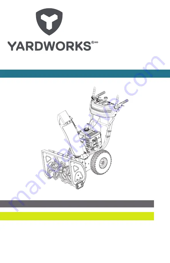
Snowblower

IMPORTANT: Please read this manual carefully before operating this snowblower and save it for reference.

 

WARNING: Machine is without engine oil. Properly fill engine oil prior to use to prevent engine damage.

REV 20230713

Summary of Contents for 060-0608-2

Page 1: ...6 523 5218 Snowblower IMPORTANT Please read this manual carefully before operating this snowblower and save it for reference WARNING Machine is without engine oil Properly fill engine oil prior to use...

Page 2: ...ntact one of our Customer Service Agents who would be happy to assist you For Customer Assistance Please Call 1 866 523 5218 TABLE OF CONTENTS 2 SAFETY INSTRUCTIONS 3 SAFETY SYMBOLS 9 OPERATION SYMBOL...

Page 3: ...ation considered important but not hazard related e g messages relating to property damage GENERAL SAFETY 1 Read the operator s manual carefully Be thoroughly familiar with the controls and the proper...

Page 4: ...ifically recommended in the manual 5 Let engine and machine adjust to outdoor temperatures before starting to clear snow 6 The operation of any powered machine can result in foreign objects being thro...

Page 5: ...the engine is hot or running 5 Allow engine to cool at least two minutes before refueling 6 Do not over fill fuel tank Keep fuel level at least 1 27 cm below bottom of filler neck to provide space fo...

Page 6: ...inspecting or repairing any parts of the snowblower ensure the auger has stopped moving Disconnect the spark plug wire and keep it away from the plug to prevent accidental starting 7 Before leaving t...

Page 7: ...damaged parts for safety Use only genuine replacement parts and accessories 21 This snowblower is not intended for use by persons including children with reduced physical sensory or mental capabilitie...

Page 8: ...e working condition Never store the machine with fuel in the fuel tank inside a building where ignition sources are present such as hot water heaters space heaters clothes dryers or any open flame sou...

Page 9: ...hot Open Flame Alert Fuel and its vapors are extremely flammable and explosive Keep fuel away from smoking open flames sparks pilot lights heat and other ignition sources Electric Shock Failure to use...

Page 10: ...e and remain behind handles until all moving parts have stopped before unclogging Hot Surface To reduce the risk of injury or damage avoid contact with any hot surface Risk of Fire Fuel and its vapors...

Page 11: ...ith a minimum octane rating of 87 and an ethanol content of less than 10 by volume Fuel Valve ON Move the fuel valve lever to the on position Fuel Valve OFF Move the fuel valve lever to the OFF positi...

Page 12: ...is inserted into the key hole Cold Prime To start a cold engine prime 3 5 times Warm Prime To start a warm engine DO NOT prime Recoil Start Pull the recoil starter grip to start manually Remove Engin...

Page 13: ...225S Start Type Electric Recoil OIL Oil Capacity 16 9 fl oz 0 5 L Oil Type 0W 30 FUEL Use clean fresh regular unleaded gasoline with a minimum octane rating of 87 and an ethanol content of less than 1...

Page 14: ...ntrol Lever H Clean out Tool I Control Panel J Handle Locking Knobs K Discharge Chute Deflector L Discharge Chute M Auger N Shave Plate O Skid Shoes P Auger Housing Q Wheels R Lower Handle S Upper Han...

Page 15: ...model no 060 0608 2 contact us 1 866 523 5218 15 Specifications A H I J E F G B C D K K N M P O L I R Q T S J J...

Page 16: ...rom the carton 3 Cut down the bottom carton to allow a flat surface area to install the assembly parts without scratching parts or cutting tires 4 Now you are ready for assembly TOOLS INCLUDED Part Pa...

Page 17: ...lat Washer 2 N A M8 45 bolt 2 13 mm wrench Curve washer 2 N A Upper Handle 1 M8 50 bolt 4 N A Curved washer 4 N A Locking knob 4 N A Speed Control Lever 1 Clip pre assembled 2 N A 8 Flat Washer preass...

Page 18: ...del no 060 0608 2 contact us 1 866 523 5218 18 Assembly Steering Trigger 2 M5 35 screw 2 Cross or Phillips Head screwdriver Wire Harness 1 preassembled on engine and panel end Cable Clamp 4 preassembl...

Page 19: ...hen pull the pin A out holding the wheel on Fig 1 Repeat on the other side Remove the wheels and carefully place the snowblower on the ground A B C Figure 1 A D B C E Figure 2 HANDLE 1 Attach the lowe...

Page 20: ...ig 3 Torque until snug Do not overtighten F G H Figure 3 INSTALL THE WHEELS Slide the wheel A onto axle B Tread pattern should face forward Place axle pin C into wheel The axle has a center hole to at...

Page 21: ...ct side Fig 5 2 Connect the other end of the connecting lever A and speed adjusting handle with clip on the base Remove the washer and clip insert as shown into the connecting base then install the wa...

Page 22: ...nug Fig 7 B A Figure 7 DISCHARGE CHUTE DEFLECTOR CABLE Locate the coiled chute deflector cable A and uncoil Open the chute deflector completely by hand then install the cylindrical end B of the cable...

Page 23: ...el A with the engine harness B The harness will make an audible click Press the lock in the red arrow then perform a pull test to confirm locked together Fig 9 A B Figure 9 TRIGGER STEERING SYSTEM Att...

Page 24: ...AMPS Connect the cable clamps A to the handle bars as shown If already connected move into the correct location and remove to position the cables and then reconnect to the handle bars as shown Make su...

Page 25: ...be used after the 5 hour initial break in period Using synthetic oil does not decrease the recommended oil change interval 20 0 20 40 Ambient temperature Recommended Engine Oil Type 28 9 F C 17 8 6 7...

Page 26: ...ing of 87 and an ethanol content of less than 10 by volume 1 Remove the fuel tank cap A Fig 15 A Figure 15 2 Add fuel to the bottom of the fuel level limit in the neck of the fuel tank Do not overfill...

Page 27: ...fuel tank Keep fuel level at least 1 27 cm below bottom of filler neck to provide space for fuel expansion 7 Replace gasoline cap and tighten securely 8 If gasoline is spilled wipe it off the engine...

Page 28: ...inside a vehicle or on a truck or trailer bed with a plastic liner Always place containers on the ground away from your vehicle before filling 12 If possible remove gas powered equipment from the truc...

Page 29: ...re tired or ill PREPARATION FOR USE 1 Disengage all clutch handles before starting the engine 2 Do not operate the equipment without wearing adequate winter garments Wear footwear which will improve f...

Page 30: ...s stopped moving Disconnect the spark plug wire and keep it away from the plug to prevent accidental starting 7 Before leaving the machine unattended disengage all control levers stop the engine and r...

Page 31: ...Be careful while working on the machine or clearing a blockage in the auger or impeller to ensure that fingers and hands do not become crushed or cut 23 Do not touch hot engine components like the muf...

Page 32: ...GGESTIONS PREPARING FOR SNOW REMOVAL IMPORTANT Before the first snowfall the area in which snow removal is to take place should be cleared of all door mats stones sticks etc which might be picked up b...

Page 33: ...NG TIPS 1 Pay attention to your body to avoid over exertion and to avoid frost bite Take breaks indoors to rest warm up 2 Whenever possible discharge snow downwind 3 Do not attempt to remove ice or ha...

Page 34: ...esults This is accomplished by having the throttle control set at fast Rabbit position Ground speed is controlled by selecting 1 2 3 4 5 or 6 with the self drive speed control lever Operate in positio...

Page 35: ...g the engine At high altitudes increased exhaust emissions can also result due to the increased enrichment of the air fuel ratio Other high altitude issues can include hard starting increased fuel con...

Page 36: ...ut off lever D to the ON position 2d Prime E 3 5 times 2e Move the choke lever C to the run position once the engine begins to run after you pull the recoil start grip or use the electric start CHOKE...

Page 37: ...lightly until you feel resistance then pull briskly Return the starter grip gently Fig 22 Figure 22 5 Alternatively for electric start plug in the supplied electrical cord into the starter Press the e...

Page 38: ...he snowblower Fig 24 When the snowblower has been put into gear pushing this lever towards the handle engages the wheels Releasing the self drive control lever causes the machine to stop moving Figure...

Page 39: ...wards the handle causes the auger and impeller to activate Releasing the auger control lever causes the auger to stop moving Figure 26 DISCHARGE HEIGHT LEVER The discharge chute deflector lever contro...

Page 40: ...ig 28 Figure 28 TRIGGER STEERING SYSTEM This model is equipped with a dual trigger steering feature A small trigger under each hand grip controls the steering of the machine 1 Engage the self drive co...

Page 41: ...llowing steps While both the drive and auger control levers are fully depressed release the auger control lever A while keeping the self drive control lever B fully depressed The clutch lock feature w...

Page 42: ...and to make any adjustments to the discharge chute needed to maximize operation To disengage the clutch lock feature simply release the self drive control lever B A Figure 30 HEATED HAND GRIPS Turn on...

Page 43: ...608 2 contact us 1 866 523 5218 43 CONTROLS LIGHTS The lights on the control panel turn on automatically when the engine is started The lights on the control panel turn off automatically when the engi...

Page 44: ...nt the shave plate to ride above the ground Loosen the bolts holding the skid shoes in place and slide the skid shoes down until they contacts the ground Re tighten the skid shoe bolts Fig 32 Figure 3...

Page 45: ...ontainer by slightly tipping the engine to tilt the oil drain downward Fig 33 Figure 33 4 Replace the drain bolt Tighten until snug 5 With the engine in a level position fill to the upper limit mark o...

Page 46: ...5 2 If the augers will not turn check to see if the pins have sheared Replacement shear pins and clips are found on the control panel and the manual bag Fig 36 Figure 36 3 Tap out broken shear pin wit...

Page 47: ...sion the transmission is disengaged Stage 2 there is tension the transmission is engaged 1 2 Figure 37 If there is no stage 2 the friction disc is near end of life Stage 1 increases slightly during lo...

Page 48: ...rol cable adjustment fails to correct the problem the friction disc may need to be replaced See Repair or Replace Friction Disc If the friction disc is ok then you should replace the cable If you find...

Page 49: ...as shown earlier Fig 42 5 Perform a speed test to confirm everything is in working order 6 Tighten the nut from earlier C ADJUST AUGER CONTROL CABLE Proper tension is important because you will want...

Page 50: ...ging If the belt isn t allowed to disengage properly you could cause premature wearing of the belt and ultimately cause belt failure Fig 43 A B Figure 43 3 With a helper operate the auger control on a...

Page 51: ...it does not open fully or does not tip down enough proceed as follows 1 Locate the chute deflector control lever on the control panel Fig 44 Figure 44 2 Move the chute deflector lever A all the way b...

Page 52: ...moving down If the deflector moves down a bit then turn the lower nut counterclockwise away from the bracket to engage the spring without moving the deflector downwards Fig 47 C Figure 47 5 Rotate th...

Page 53: ...f the M8 bolt B on the right side of the lever for the M8 lock nut Fig 49 B A Figure 49 3 To increase deflector tension to prevent unwanted deflector movement from heavy snow use a 10 mm wrench on the...

Page 54: ...refully pivot the snowblower up and forward so that it rests on the auger housing Place a piece of cardboard or moving blanket on the ground before tipping forward Make sure all fluids are removed and...

Page 55: ...ance 4 Unhook the connector D in the control handle You may have to move the control handle to make this easier to remove Fig 52 D Figure 52 5 Unhook the spring E from the drive plate F Fig 53 6 Perfo...

Page 56: ...ur snowblower s auger cable proceed as follows 1 Remove the plastic belt cover on the front of the engine by removing two M6 12 bolts and flat washers Fig 54 Figure 54 B A Figure 55 2 Locate the auger...

Page 57: ...ay have to move the control handle to make this easier to remove Fig 56 C Figure 56 5 Remove the auger plate D as shown on the front of the engine by removing two M6 12 bolts E Fig 57 E D Figure 57 6...

Page 58: ...nnected Tools required 10 mm wrench 13 mm wrench To remove and replace your snowblower s auger belt proceed as follows 1 Remove the plastic belt cover on the front of the engine by removing two M6 12...

Page 59: ...Unhook the spring B from the auger plate C Fig 61 B C Figure 61 4 Slip the old auger drive belt off the engine pulley Fig 62 Figure 62 5 Remove auger housing from engine base by removing three M8 x 1...

Page 60: ...to remove belt Push the auger idler pulley E toward the large auger pulley to release the brake and pull the belt off from the large pulley Fig 64 7 Perform the steps in reverse with the new belt 8 Pe...

Page 61: ...ows 1 Carefully pivot the snowblower up and forward so that it rests on the auger housing Place a piece of cardboard or moving blanket on the ground before tipping forward Make sure all fluids are rem...

Page 62: ...a 22 mm or adjustable wrench C to hold the center of the hex shaft and use a 13 mm socket to remove the bolt on the left side Fig 67 5 Slide out the hex shaft Punch the shaft out from the left side M...

Page 63: ...t overtighten Fig 70 Figure 70 8 Clean the aluminum friction disc by wiping down with a clean cloth and follow the previous steps in reverse order to reassemble hexagon shaft parts Make sure the parts...

Page 64: ...or Phillips Head screwdriver 10 mm size wrench To replace your snowblower s trigger steering system proceed as follows A Figure 72 A B Figure 73 2 Carefully pivot the snowblower up and forward so tha...

Page 65: ...the smaller cover squeeze and remove the strain relief from the metal plate This will dislodge the cable from the smaller base frame cover Fig 74 Figure 75 5 Unhook the connector Fig 75 6 On the trigg...

Page 66: ...sure all fluids are removed and spark plug is disconnected Tools required 13 mm wrench Needle nose pliers To remove and replace your snowblower s chute deflector cable proceed as follows 1 Adjust def...

Page 67: ...boot and completely loosen the top nut C on the end of the cable as shown so you can slide the cable out Fig 80 C Figure 80 4 Pull the cable downwards and remove the cable from the connector bracket o...

Page 68: ...ntrol panel location the chute deflector cable remove both the pin D and cotter pin E Fig 83 E D Figure 83 7 Completely loosen both nuts F on this cable Fig 84 F Figure 84 8 Remove the cable from the...

Page 69: ...plug is disconnected Tools required 10 mm wrench To replace your snowblower s clutch lock cable proceed as follows 1 On the underside of the control panel loosen the top nut A from the clutch cable on...

Page 70: ...connector C from the self drive control lever Fig 88 C Figure 88 4 Remove the two M6 x 20 bolts and lock washers from the plate underneath the control panel near the auger control lever Fig 89 Figure...

Page 71: ...om the spring barrel by turning counterclockwise Fig 91 Figure 91 7 Remove spring assembly Fig 92 Figure 92 8 Remove the cable compression spring barrel Fig 93 9 Reassemble new clutch cable in reverse...

Page 72: ...Use a Phillips screwdriver to remove the M5 x 10 cross recessed bolt B Fig 94 A B Figure 94 3 Use Low Temp NLGI 2 grease lithium base in a grease gun 4 Attach grease gun to zerk fitting Fig 95 5 Add...

Page 73: ...ark Arrester optional parts Clean Auger Gear Box Grease Tire Pressure Check adjust Skid Shoe Check adjust height Idle Speed Check adjust 1 Valve Clearance Check adjust 1 Fuel Tank and Strainer Clean 1...

Page 74: ...ns 2 Start the engine and let it run until it stops due to lack of fuel 3 Change the engine oil if it has not been done for 3 months 4 Remove the spark plug and empty a little engine oil about 1 oz 30...

Page 75: ...er drive belt broken Replace the belt Shear pin broken Replace the shear pin Auger does not stop when the lever is released Auger drive belt is out of adjustment Adjust the belt cable to decrease tens...

Page 76: ...drive disc skid shoes and shave plate These parts are warranted to the original purchaser to be free from defects in material and workmanship for a period of two hundred seventy 270 days from the dat...

Page 77: ...in connection with the sale use or inability to use this product NOTICE TO CONSUMER This warranty gives you specific legal rights and you may have other rights which may vary from province to provinc...

Page 78: ...ed part on your engine is defective in materials or workmanship the part will be repaired or replaced by CPE OWNER WARRANTY RESPONSIBILITIES As the small off road engine SORE owner you are responsible...

Page 79: ...r replaced under the ECS Warranty shall be warranted for the remainder of the ECS Warranty Period 3c Any warranted emissions related part which is scheduled for replacement as required maintenance in...

Page 80: ...Fuel Tank Fuel Cap Fuel Lines for liquid fuel and fuel vapors Fuel Line Fittings Clamps Pressure Relief Valves Control Valves Control Solenoids Electronic Controls Vacuum Control Diaphragms Control C...

Reviews: