56
8. When a trouble occurs
Message error table
Show the error codes on Table 8.1 below.
Buzz and stop its operation at occurring errors on this Equipment.
Pressing any key (except for the
key) will stop the buzzer sound. When three minutes have passed
as it is, the buzzer starts to sound again.
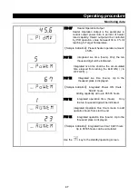
The Top screen shows an error code and the Bottom screen shows the error name. Note the error code,
immediately turn power off and stop operating the unit.
Table 8.1
Table of Error Code
Error
Display
Error Code Name
Causes and their solutions
ER01
SENS
Sensor Failure
Fail in temperature sensor.
Open circuit on temperature sensor line.
Detect temperature out of its designed range.
Contact with local dealer or Yamato Customer Service Center.
ER02
TRIAC
TRIAC short circuit error
Short on TRIAC circuit.
Fail on Current Transformation (CT) sensor.
Contact with local dealer or Yamato Customer Service Center.
ER03
HEAT
Heater Line
Disconnection
Heater Line Disconnection
Fail on Current Transformation (CT) sensor.
The source voltage has dropped.
Contact the general customer service center.
ER07
OHEAT
Independent
Overheat Prevention
Device(IOPD)
activated
Activate Independent Overheat Prevention Device
(IOPD).
Turn ELB on again and check both Furnace temperature and
setting Temperature of IOPD.
Contact with local dealer or Yamato Customer Service
Center, if this Equipment is not energized at ELB on.
ER10
RELAY
Main Relay Contact
melted
Check at turning ELB on again:
Melt down the contact point of Main Relay.
Fail on Current Transformation (CT) sensor(s).
Contact with local dealer or Yamato Customer Service
Center.
ER14
RAM
RAM Failure
Reduced capacity or
end of use life of the
backup battery
Check at turning ELB on again:
RAM Failure
:
Reset power once.
Reduced capacity or end of use life of the backup
battery
:
Contact with local dealer or Yamato Customer Service
Center, if this error cannot be reset by ELB on.
Must be replaced backup battery.
Summary of Contents for FP102
Page 67: ...64 12 Wiring diagram FP102 Wiring diagram Dotted line means optional parts ...
Page 68: ...65 12 Wiring diagram FP302 Wiring diagram Dotted line means optional parts ...
Page 69: ...66 12 Wiring diagram FP312 Wiring diagram Dotted line means optional parts ...
Page 70: ...67 12 Wiring diagram FP412 Wiring diagram Dotted line means optional parts ...

