21
4. Operating procedure
Auto stop operation
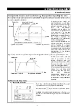
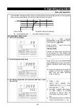
This operation mode is used to automatically stop operation by setting the timer.
The operation mode where operation is automatically stopped by setting an operation duration.(when
you set an operation duration)
※
When you set a time, the
wait function will be activated,
the mode will remain “waiting”
without counting down the
time
until
temperature
indication will be within the
wait deviation range between
-3
℃
and +6
℃
to the set
temperature. Counting down
starts when the temperature in
the
furnace
reaches
the
temperature -3
℃
(indication)
to the set temperature.
Even if the temperature in the
furnace (indication) the mode
will be “waiting” if the lower
limit of the wait width deviation
is exceeded and time counting
down will not occur until the
temperature in the furnace
(indication) returns.
Operation mode where operation stops automatically at the set time (when an operation time is set)
※
The wait function will not
work if you select a time
setting. Operation will stop
when the set time comes. The
time you can set is up to 24
hours from the present time.
When a power failure occurred
before the set time and
continued after that and then
the
unit
recovered
automatically, operation will
continue to the next set time
so remember to stop operation
manually.
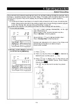
Set Automatic Stop mode
1
Turn on the controller
Turn on(
|
) Earth Leakage Breaker (ELB) on the upper
right side wall of this Equipment. (
Idle State
)
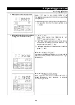
Press and hold key to turn on the controller power.
Indicate circulating liquid temperature in Furnace on
Top Screen and indicate target temperature on Bottom
Screen.
Temperature
Set temp.
Lower limit of the wait
width deviation
Door open
Timer start
①
Timer start
②
Wait
①
Wait
②
Actual elapsed time=set time (timer start
①
+
②
)+(Wait
①
+
②
)
Operation start (manual)
Operation stop (automatic)
Time
Temperature
Set temp.
Door open
Operation start (manual)
Operation stop (automatic)
Time
Set time
Summary of Contents for FP102
Page 67: ...64 12 Wiring diagram FP102 Wiring diagram Dotted line means optional parts ...
Page 68: ...65 12 Wiring diagram FP302 Wiring diagram Dotted line means optional parts ...
Page 69: ...66 12 Wiring diagram FP312 Wiring diagram Dotted line means optional parts ...
Page 70: ...67 12 Wiring diagram FP412 Wiring diagram Dotted line means optional parts ...

