30
4. Operating procedure
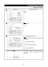
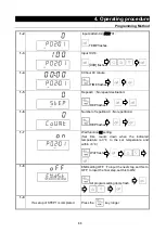
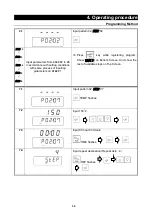
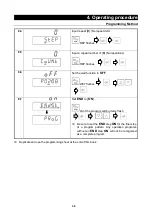
Programming Method
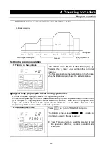
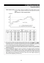
Sample program setting In this example, 8 steps are registered in the program pattern 2, steps
from 4 to 7 will be repeated 5 times and the whole session will end at the
step 8.
Note: Steps 4 to 7 will be repeated 6 times.
Pattern No
Step
Set temp. Set time
Repeat
dstn.
Repeat No.
Wait
End
P
**
:01
P02:
**
TEMP
TIME
REP(STEP)
REP(COUNT)
WAIT
ENDST
02
01
100
00:00
0
0
ON
OFF
02
100
01:15
0
0
OFF
OFF
03
150
00:00
0
0
ON
OFF
04
150
02:00
0
0
OFF
OFF
05
200
01:00
0
0
ON
OFF
06
200
01:30
0
0
OFF
OFF
07
150
00:00
4
5
ON
OFF
08
150
00:30
0
0
OFF
ON
※
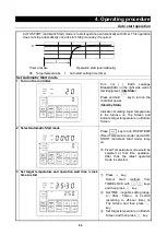
When set time for heating or cooling steps beyond the heating or the cooling capacity (0 minute in
the example) of the unit, it will operate at the full power for a short time at wait [
ON
]. At wait [
OFF
],
the step will proceed to the next one irrespective of whether the set temperature is attained or not
and you need to take care for setting a wait for heating or cooling for a short period.
※
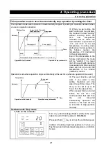
If you set a time beyond the beyond the temperature increase and decrease time, temperature
increase and decrease will be controlled at the specified rate so that the set temperature will be
attained in the set time.
※
If you set operation with temperature increase or decrease in the program operation, temperature
increase and decrease operation will be carried out at the specified rate from the current
temperature to the set temperature for the set time. With the wait “ON” setting, the step will
proceed to the next one when the measured temperature is within the wait range. With the wait
“OFF” setting, the step will proceed to the next one when the set time elapses irrespective of
whether the set temperature is reached or not.
0 min.
0 min.
1 h. 15 min.
2 h.
1 h.
1 h. 15 min.
30 min.
0 min.
Setting heating/cooling in minimum time
Setting heating in a fixed rate heating time
Time
Repeat five times
Temperature
Time
Summary of Contents for FP102
Page 67: ...64 12 Wiring diagram FP102 Wiring diagram Dotted line means optional parts ...
Page 68: ...65 12 Wiring diagram FP302 Wiring diagram Dotted line means optional parts ...
Page 69: ...66 12 Wiring diagram FP312 Wiring diagram Dotted line means optional parts ...
Page 70: ...67 12 Wiring diagram FP412 Wiring diagram Dotted line means optional parts ...

