48
4. Operating procedure
Independent Overheat Prevention Device
This Equipment has redundant safety devices-1) Automatic Overheat Prevention (automatic reset)
function on the Controller, and -2) Independent Overheat Prevention Device (IOPD) with
independent power, circuit and sensor away from the Controller.
Main Relay of this Controller will be shut heater output power off when one of safety devices is
activated at Furnace internal temperature beyond its setting temperature.
Those functions will avail at Earth Leakage Breaker(ELB) ON(
|
).
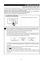
Set temperature on Independent
Overheat Prevention Device(IOPD)
※
Set temperature with ▼▲ keys on its panel.
May stop its operation by activating
Independent Overheat Prevention Device(
IOPD) when the
difference between set temperature on IOPD and Target Temperature will be too close each other.
Must set IOPD temperature at least 100
℃
higher than Target Temperature.
The temperature is set at 1250
℃
at the factory shipping.
Note that the objective of this IOPD will not protect for samples but from overheating this Equipment.
Note that this can prevent accidents as a result of using explosive or combustible substances.
Factory settings and setting temperature ranges are as shown below:
Model
Set temperature at
shipment
Setting temperature
range
FP102/302/312/412
1250
℃
0
℃~
1300
℃
Control Furnace stable at required temperature first, and let IOPD setting temperature down by
1
℃
and then find out IOPD activating temperature, if IOPD will get to be activated at required
temperature.
Must wait for 5(five) seconds for the next 1
℃
down of IOPD setting temperature, because its
function will be operated to need some times.
Display
ER07
on Top Screen on Control Panel, if this IOPD is activated.
When you have set an operation temperature you want for IOPD , recording of the set
temperature takes several seconds and you need to wait for about five seconds before turning
the ELB off.
Summary of Contents for FP102
Page 67: ...64 12 Wiring diagram FP102 Wiring diagram Dotted line means optional parts ...
Page 68: ...65 12 Wiring diagram FP302 Wiring diagram Dotted line means optional parts ...
Page 69: ...66 12 Wiring diagram FP312 Wiring diagram Dotted line means optional parts ...
Page 70: ...67 12 Wiring diagram FP412 Wiring diagram Dotted line means optional parts ...

