14
4. Operating procedure
Date & Time setting
The controller of this product keeps backup memory for customer settings including the calendar, timer
settings, or operation programs using the built-in battery. This battery will hold data for about five years
even if you turn power of the unit off. (Battery life will change depending on specific operating
conditions.)
※
Contact with Yamato local dealer or Yamato Customer Service Center in case of replacing this
battery. Make backup data file of the existing program data in case of being processed program
mode. See “Backup data saving/reading out/resetting” on page 45.
Set up date & time properly in accordance with local time after replacing with new battery.
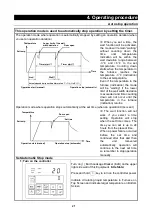
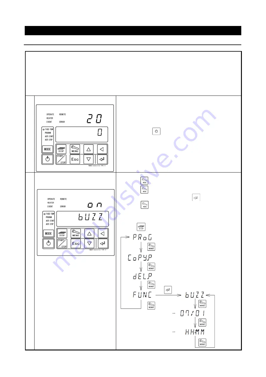
1
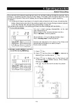
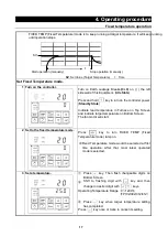
Turn on the controller.
Turn on(
|
) Earth Leakage Breaker(ELB) on the right
side of this Equipment.
Bottom Screen of the controller indicate clock time.
This is “
Idle State
” of this Equipment.
Press and hold
key to display standby screen.
This is “
Standby State
” of this Equipment.
Indicate read temperature in Furnace on Top Screen and
indicate target temperature on Bottom Screen.
The fan motor will start.
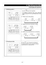
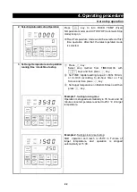
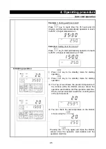
2 Display year/month/date and time
on each Screen by MENU key.
①
Press
key.
②
Press
key few times until [
FUNC
] is indicated on
Bottom Screen and then press
key.
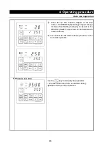
③
Press
key to display year on Top Screen and
month/date/time on Bottom Screen, When Bottom
Screen show [
BUZZ
].
The
key can be used to reverse the process.
Summary of Contents for FP102
Page 67: ...64 12 Wiring diagram FP102 Wiring diagram Dotted line means optional parts ...
Page 68: ...65 12 Wiring diagram FP302 Wiring diagram Dotted line means optional parts ...
Page 69: ...66 12 Wiring diagram FP312 Wiring diagram Dotted line means optional parts ...
Page 70: ...67 12 Wiring diagram FP412 Wiring diagram Dotted line means optional parts ...

