Setting the Input Channels from the Display
81
01V96 Version 2—Owner’s Manual
Input Channels
7
Gating Input Channels
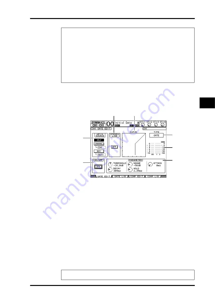
To set the Input Channel gates, use the [SEL] buttons to select the desired Input Channel,
then press the DISPLAY ACCESS [DYNAMICS] button, then press the [F1] button. The
Dynamics | Gate Edit page appears.
A
KEYIN SOURCE
Select one of the following buttons to determine the trigger source for the cur-
rently-selected Input Channel’s gate.
•
SELF
...............................The selected channel’s own input signal is the trigger source.
•
CHANNEL
....................Another Channel’s input signal is the trigger source. Select the
desired channel in the parameter box below the CHANNEL
button.
•
AUX
................................An Aux Send signal is the trigger source. Select the desired bus
in the parameter box below the AUX button.
B
STEREO LINK
This parameter’s ON/OFF button enables you to pair gates for stereo operation even
when the Input Channels are not paired.
C
CURVE
This area displays the current gate curve.
D
TYPE
This area displays the current gate type (GATE or DUCKING).
Tip:
• This function is unavailable for the ST IN Channels.
• The delay time range depends on the sampling rate at which the 01V96 is operating. (For
example, at 44.1 kHz, the range is 0 through 984.1 msec.)
• If you select the DELAY SCALE meter or feet button, the distance value can be converted to
the delay time based on sonic speeds (about 340 m/sec at 15 degrees Celsius). This option is
useful if you wish to correct the timing difference between two sound sources that are far
apart.
• If you select the DELAY SCALE beat button, a parameter box for setting a note that repre-
sents the beat and a parameter box for a tempo (BPM) setting appear below the DELAY
SCALE parameter. Setting the note and BPM settings in these parameter boxes enables you
to set a delay time that synchronizes to the song tempo.
Note:
You cannot change the gate type on this page. To change the gate type, recall a program
that uses the desired gate type from the Gate library.
4
5
7
6
1
3
2
Summary of Contents for O1V96
Page 1: ...E Owner s Manual Keep This Manual For Future Reference ...
Page 46: ...46 Chapter 4 Connections and Setup 01V96 Version 2 Owner s Manual ...
Page 96: ...96 Chapter 7 Input Channels 01V96 Version 2 Owner s Manual ...
Page 108: ...108 Chapter 8 Bus Outs 01V96 Version 2 Owner s Manual ...
Page 130: ...130 Chapter 10 Input Output Patching 01V96 Version 2 Owner s Manual ...
Page 148: ...148 Chapter 12 Surround Pan 01V96 Version 2 Owner s Manual ...
Page 164: ...164 Chapter 14 Internal Effects 01V96 Version 2 Owner s Manual ...
Page 188: ...188 Chapter 16 Libraries 01V96 Version 2 Owner s Manual ...
Page 228: ...228 Chapter 18 MIDI 01V96 Version 2 Owner s Manual ...
Page 325: ...01V96 Block Diagram ...


