50
Chapter 5—Tutorial
01V96 Version 2—Owner’s Manual
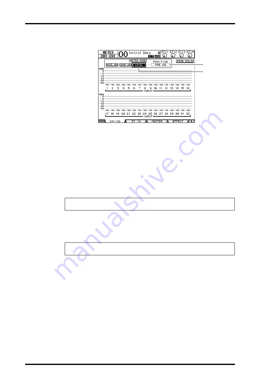
The CH1-32 page enables you to view Input Channel 1–32 levels and compressor and gate
gain reduction amounts.
4 Make sure that the LEVEL button (
1
) is turned on in the METER MODE sec-
tion.
The METER MODE section enables you to select the type of signals displayed on the
meters. If any button other than the LEVEL button is turned on, move the cursor to the
LEVEL button, then press [ENTER].
5 Move the cursor to the POSITION parameter box (
2
) to the right of the
LEVEL button, rotate the Parameter wheel or press the [INC]/[DEC] buttons
to select “POST FADER,” then press [ENTER].
The POSITION parameter indicates the metering position. When “POST FADER” is
selected, the meters indicate the post-fader signal levels.
6 Make sure that [ON] button indicators 1–12 are lit, then raise faders 1–12 to
0dB.
7 While the musicians play the musical instruments, check the input channel
levels using the level meters on the display.
Pairing Channels
On the 01V96, you can pair adjacent odd-even channels for stereo operation. Faders and
most mix parameters of paired channels (excluding the Input Patch, phase, routing, and
pan parameters) are linked. Pairing Input Channels is useful when you are connecting ste-
reo sources, such as a rhythm machine or synthesizer.
1 To pair adjacent odd-even Input Channels, press and hold the [SEL] button
for one of the channels you wish to pair, and press the [SEL] button for the
adjacent channel.
The corresponding two channels are paired, and the settings (such as faders, channel on/off,
etc.) of the first channel are copied to the second channel. Subsequently, adjusting the
linked parameters of one of the paired channels will adjust the parameters of its partner in
the same way.
Tip:
If you set the POSITION parameter to “PRE EQ,” the pre-EQ input levels are metered.
If you set the parameter to “PRE FADER,” the post-EQ and pre-fader input levels are metered.
Tip:
If the meters reach the “OVER” level, make sure that the faders are set to 0dB, then lower
the corresponding [GAIN] controls.
1
2
Summary of Contents for O1V96
Page 1: ...E Owner s Manual Keep This Manual For Future Reference ...
Page 46: ...46 Chapter 4 Connections and Setup 01V96 Version 2 Owner s Manual ...
Page 96: ...96 Chapter 7 Input Channels 01V96 Version 2 Owner s Manual ...
Page 108: ...108 Chapter 8 Bus Outs 01V96 Version 2 Owner s Manual ...
Page 130: ...130 Chapter 10 Input Output Patching 01V96 Version 2 Owner s Manual ...
Page 148: ...148 Chapter 12 Surround Pan 01V96 Version 2 Owner s Manual ...
Page 164: ...164 Chapter 14 Internal Effects 01V96 Version 2 Owner s Manual ...
Page 188: ...188 Chapter 16 Libraries 01V96 Version 2 Owner s Manual ...
Page 228: ...228 Chapter 18 MIDI 01V96 Version 2 Owner s Manual ...
Page 325: ...01V96 Block Diagram ...


