ENGINE
3-20
k. Engage the clutch by turning the manual
clutch operation bolt in direction “b” until it
stops.
TIP
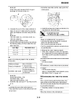
The following illustration shows the manual
clutch operation bolt when viewed from the rear
of the vehicle with the swingarm removed.
l. Repeat steps (i) to (k) until all of the air bub-
bles have disappeared from the clutch fluid in
the plastic hose of the vacuum/pressure
pump gauge set.
m. Tighten the bleed screw to specification.
n. Manually engage and disengage the clutch
30 times using the manual clutch operation
bolt.
o. Add the recommended clutch fluid to the
proper level.
Refer to “CHECKING THE CLUTCH FLUID
LEVEL (FJR13AE)” on page 3-18.
▲▲▲
▲
▲ ▲▲▲
▲
▲ ▲▲▲
▲
▲ ▲▲▲
▲
▲ ▲▲▲
▲
▲ ▲▲▲
▲
▲▲▲
3. Check:
• Pressure plate stroke
▼▼▼
▼
▼ ▼▼▼
▼
▼ ▼▼▼
▼
▼ ▼▼▼
▼
▼ ▼▼▼
▼
▼ ▼▼▼
▼
▼▼▼
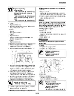
a. Remove the pickup rotor cover bolts “1”.
b. Remove the clutch cover “2”.
Refer to “CLUTCH” on page 5-46.
c. Manually engage and disengage the clutch
using the clutch operation bolt “3” five times,
each time for less than 1 second.
TIP
Turn the clutch operation bolt in a continuous
motion, without allowing the pressure plate to
stop in mid-stroke.
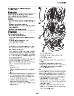
d. Install a suitable bracket “4”, the magnet base
B “5” and the dial gauge & stand set “6”.
T
R
.
.
Bleed screw
6 Nm (0.6 m·kg, 4.3 ft·lb)
4
b
a
2
1
Magnet base B
90890-06844
Magnetic base stand
YU-A8438
Dial gauge & stand set
90890-01252
a. 100 mm (3.94 in)
b. 20 mm (0.79 in)
c. 1.5 mm (0.06 in)
d. 64 mm (2.52 in)
e. M6
×
40 mm bolt
f.
5 mm (0.20 in)
g. 60 mm (2.36 in)
3
6
4
5
a
a
b
c
d
e
f
g
Summary of Contents for FJR13AY 2009
Page 1: ...2009 SERVICE MANUAL FJR13AY C FJR13AEY C LIT 11616 22 73 3P6 28197 12 ...
Page 6: ......
Page 8: ......
Page 80: ...LUBRICATION SYSTEM CHART AND DIAGRAMS 2 31 EAS20410 LUBRICATION DIAGRAMS 5 6 7 1 2 3 4 ...
Page 82: ...LUBRICATION SYSTEM CHART AND DIAGRAMS 2 33 1 3 2 ...
Page 83: ...LUBRICATION SYSTEM CHART AND DIAGRAMS 2 34 1 Main axle 2 Drive axle 3 Oil delivery pipe 1 ...
Page 84: ...LUBRICATION SYSTEM CHART AND DIAGRAMS 2 35 6 5 4 3 2 1 ...
Page 86: ...LUBRICATION SYSTEM CHART AND DIAGRAMS 2 37 1 2 3 4 5 6 7 8 9 ...
Page 88: ...LUBRICATION SYSTEM CHART AND DIAGRAMS 2 39 4 5 3 2 1 9 8 6 7 ...
Page 92: ...COOLING SYSTEM DIAGRAMS 2 43 A A 7 1 2 3 4 5 5 7 8 6 8 9 10 11 12 ...
Page 98: ...CABLE ROUTING FJR13A 2 49 2 3 4 5 6 7 8 9 11 10 12 13 14 15 16 A B C D E F 1 1 ...
Page 100: ...CABLE ROUTING FJR13A 2 51 1 2 3 4 5 6 7 8 A B C D E 9 10 11 12 13 ...
Page 108: ...CABLE ROUTING FJR13A 2 59 1 2 3 4 A B B C D E ...
Page 110: ...CABLE ROUTING FJR13A 2 61 A 1 A A B P O C D E F G H I J K L M N 2 3 4 5 6 7 8 9 10 A 11 ...
Page 118: ...CABLE ROUTING FJR13AE 2 69 2 3 4 5 6 7 8 9 11 12 13 14 15 16 17 A B C E D F 1 1 H 10 18 G ...
Page 120: ...CABLE ROUTING FJR13AE 2 71 1 2 3 4 5 6 7 8 A B C D E 9 10 11 12 13 ...
Page 128: ...CABLE ROUTING FJR13AE 2 79 1 4 2 5 6 A B C D D E 3 F G ...
Page 130: ...CABLE ROUTING FJR13AE 2 81 A 1 A A B P O C D E F G H I J K L M N 2 3 4 5 6 7 8 9 10 A 11 ...
Page 134: ...CABLE ROUTING FJR13AE 2 85 ...
Page 137: ......
Page 196: ...GENERAL CHASSIS 4 11 b a 1 2 ...
Page 302: ...SHAFT DRIVE 4 117 ...
Page 326: ...CAMSHAFTS 5 21 ...
Page 424: ...CONNECTING RODS AND PISTONS 5 119 ...
Page 462: ...WATER PUMP 6 15 ...
Page 473: ...THROTTLE BODIES 7 10 ...
Page 474: ...AIR INDUCTION SYSTEM 7 11 EAS27040 AIR INDUCTION SYSTEM 1 2 3 4 5 1 1 1 1 2 2 5 2 3 3 4 7 8 6 ...
Page 483: ......
Page 495: ...IGNITION SYSTEM 8 12 ...
Page 511: ...ELECTRIC STARTING SYSTEM 8 28 ...
Page 513: ...CHARGING SYSTEM 8 30 2 Rectifier regulator 3 AC magneto 8 Main fuse 10 Battery ...
Page 515: ...CHARGING SYSTEM 8 32 ...
Page 539: ...COOLING SYSTEM 8 56 ...
Page 587: ...FUEL PUMP SYSTEM 8 104 ...
Page 599: ...ACCESSORY BOX SYSTEM 8 116 ...
Page 609: ...ABS ANTI LOCK BRAKE SYSTEM 8 126 ...
Page 698: ...ELECTRICAL COMPONENTS 8 215 FJR13A 5 1 3 2 17 8 10 11 12 13 14 15 16 7 6 4 9 ...
Page 700: ...ELECTRICAL COMPONENTS 8 217 FJR13AE 13 16 18 17 2 3 4 5 6 7 8 1 9 10 11 12 15 14 19 ...
Page 702: ...ELECTRICAL COMPONENTS 8 219 FJR13AE 1 19 3 2 5 7 9 8 12 13 14 15 16 11 10 18 17 6 4 ...
Page 730: ...ELECTRICAL COMPONENTS 8 247 ...
Page 739: ......
Page 740: ...YAMAHA MOTOR CO LTD 2500 SHINGAI IWATA SHIZUOKA JAPAN ...


