ENGINE
3-8
Example:
If the valve pad is marked “155”, the pad
thickness is 1.55 mm (0.061 in).
d. Calculate the sum of the values obtained in
steps (b) and (c) to determine the required
valve pad thickness and the valve pad num-
ber.
Example:
1.55 mm (0.061 in) + 0.03 mm (0.001 in) =
1.58 mm (0.062 in)
The valve pad number is 158.
e. Round off the valve pad number according to
the following table, and then select the suit-
able valve pad.
TIP
Refer to the following table for the available
valve pads.
Example:
Valve pad number = 158
Rounded value = 160
New valve pad number = 160
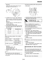
f. Install the new valve pad “1” and the valve lift-
er “2”.
TIP
• Lubricate the valve lifter with engine oil.
• The valve lifter must turn smoothly when rotat-
ed by hand.
• Install the valve lifter and the valve pad in the
correct place.
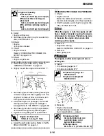
g. Install the exhaust and intake camshafts, tim-
ing chain and camshaft caps.
TIP
• Refer to “CAMSHAFTS” on page 5-13.
• Lubricate the camshaft bearings, camshaft
lobes and camshaft journals.
• First, install the exhaust camshaft.
• Turn the crankshaft clockwise several full turns
to seat the parts.
h. Measure the valve clearance again.
i. If the valve clearance is still out of specifica-
tion, repeat all of the valve clearance adjust-
ment steps until the specified clearance is
obtained.
▲▲▲
▲
▲ ▲▲▲
▲
▲ ▲▲▲
▲
▲ ▲▲▲
▲
▲ ▲▲▲
▲
▲ ▲▲▲
▲
▲▲▲
8. Install:
• All removed parts
TIP
For installation, reverse the removal procedure.
9. Adjust:
• Throttle cable free play
Refer to “ADJUSTING THE THROTTLE CA-
BLE FREE PLAY” on page 3-10.
EAS20570
SYNCHRONIZING THE THROTTLE BODIES
TIP
Prior to synchronizing the throttle bodies, the
valve clearance and the engine idling speed
should be properly adjusted and the ignition tim-
ing should be checked.
1. Stand the vehicle on a level surface.
TIP
Place the vehicle on the centerstand.
Last digit
Rounded value
0, 1, 2
0
3, 4, 5, 6
5
7, 8, 9
10
Valve pad range
Nos. 120–240
Valve pad thickness
1.20–2.40 mm
(0.0472–0.0945 in)
Available valve pads
25 thicknesses in
0.05 mm (0.002 in)
increments
T
R
.
.
Camshaft cap bolt
10 Nm (1.0 m·kg, 7.2 ft·lb)
Summary of Contents for FJR13AY 2009
Page 1: ...2009 SERVICE MANUAL FJR13AY C FJR13AEY C LIT 11616 22 73 3P6 28197 12 ...
Page 6: ......
Page 8: ......
Page 80: ...LUBRICATION SYSTEM CHART AND DIAGRAMS 2 31 EAS20410 LUBRICATION DIAGRAMS 5 6 7 1 2 3 4 ...
Page 82: ...LUBRICATION SYSTEM CHART AND DIAGRAMS 2 33 1 3 2 ...
Page 83: ...LUBRICATION SYSTEM CHART AND DIAGRAMS 2 34 1 Main axle 2 Drive axle 3 Oil delivery pipe 1 ...
Page 84: ...LUBRICATION SYSTEM CHART AND DIAGRAMS 2 35 6 5 4 3 2 1 ...
Page 86: ...LUBRICATION SYSTEM CHART AND DIAGRAMS 2 37 1 2 3 4 5 6 7 8 9 ...
Page 88: ...LUBRICATION SYSTEM CHART AND DIAGRAMS 2 39 4 5 3 2 1 9 8 6 7 ...
Page 92: ...COOLING SYSTEM DIAGRAMS 2 43 A A 7 1 2 3 4 5 5 7 8 6 8 9 10 11 12 ...
Page 98: ...CABLE ROUTING FJR13A 2 49 2 3 4 5 6 7 8 9 11 10 12 13 14 15 16 A B C D E F 1 1 ...
Page 100: ...CABLE ROUTING FJR13A 2 51 1 2 3 4 5 6 7 8 A B C D E 9 10 11 12 13 ...
Page 108: ...CABLE ROUTING FJR13A 2 59 1 2 3 4 A B B C D E ...
Page 110: ...CABLE ROUTING FJR13A 2 61 A 1 A A B P O C D E F G H I J K L M N 2 3 4 5 6 7 8 9 10 A 11 ...
Page 118: ...CABLE ROUTING FJR13AE 2 69 2 3 4 5 6 7 8 9 11 12 13 14 15 16 17 A B C E D F 1 1 H 10 18 G ...
Page 120: ...CABLE ROUTING FJR13AE 2 71 1 2 3 4 5 6 7 8 A B C D E 9 10 11 12 13 ...
Page 128: ...CABLE ROUTING FJR13AE 2 79 1 4 2 5 6 A B C D D E 3 F G ...
Page 130: ...CABLE ROUTING FJR13AE 2 81 A 1 A A B P O C D E F G H I J K L M N 2 3 4 5 6 7 8 9 10 A 11 ...
Page 134: ...CABLE ROUTING FJR13AE 2 85 ...
Page 137: ......
Page 196: ...GENERAL CHASSIS 4 11 b a 1 2 ...
Page 302: ...SHAFT DRIVE 4 117 ...
Page 326: ...CAMSHAFTS 5 21 ...
Page 424: ...CONNECTING RODS AND PISTONS 5 119 ...
Page 462: ...WATER PUMP 6 15 ...
Page 473: ...THROTTLE BODIES 7 10 ...
Page 474: ...AIR INDUCTION SYSTEM 7 11 EAS27040 AIR INDUCTION SYSTEM 1 2 3 4 5 1 1 1 1 2 2 5 2 3 3 4 7 8 6 ...
Page 483: ......
Page 495: ...IGNITION SYSTEM 8 12 ...
Page 511: ...ELECTRIC STARTING SYSTEM 8 28 ...
Page 513: ...CHARGING SYSTEM 8 30 2 Rectifier regulator 3 AC magneto 8 Main fuse 10 Battery ...
Page 515: ...CHARGING SYSTEM 8 32 ...
Page 539: ...COOLING SYSTEM 8 56 ...
Page 587: ...FUEL PUMP SYSTEM 8 104 ...
Page 599: ...ACCESSORY BOX SYSTEM 8 116 ...
Page 609: ...ABS ANTI LOCK BRAKE SYSTEM 8 126 ...
Page 698: ...ELECTRICAL COMPONENTS 8 215 FJR13A 5 1 3 2 17 8 10 11 12 13 14 15 16 7 6 4 9 ...
Page 700: ...ELECTRICAL COMPONENTS 8 217 FJR13AE 13 16 18 17 2 3 4 5 6 7 8 1 9 10 11 12 15 14 19 ...
Page 702: ...ELECTRICAL COMPONENTS 8 219 FJR13AE 1 19 3 2 5 7 9 8 12 13 14 15 16 11 10 18 17 6 4 ...
Page 730: ...ELECTRICAL COMPONENTS 8 247 ...
Page 739: ......
Page 740: ...YAMAHA MOTOR CO LTD 2500 SHINGAI IWATA SHIZUOKA JAPAN ...


