

POWR
5-5
6D45F11
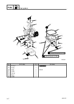
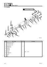
Power unit
5.
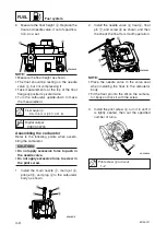
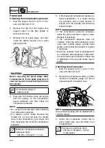
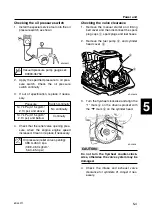
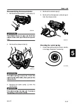
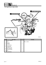
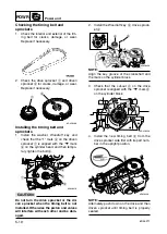
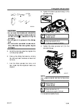
Turn the flywheel clockwise and align the
“2” mark
c
on the driven sprocket with
the “
▼
” mark
b
on the cylinder head.
c
C
Do not turn the flywheel counter-clock-
wise, otherwise the valve system may be
damaged.
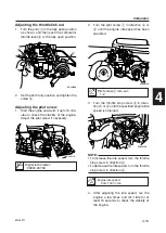
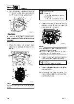
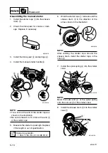
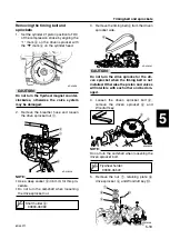
6.
Check the intake and exhaust valve
clearance for cylinders #2. Adjust if nec-
essary.
NOTE:
Adjust the valve clearance when the engine
is cold.
d
e
6D450010
6D450080
#1
EX
#1
IN
#2
IN
#2
EX
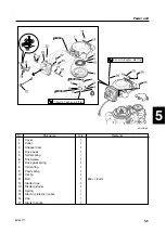
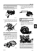
7.
Loosen the locknut
4
, and then turn the
adjusting screw
5
until the specified
valve clearance is obtained.
NOTE:
9
To decrease the valve clearance, turn the
adjusting screw clockwise.
9
To increase the valve clearance, turn the
adjusting screw counterclockwise.
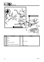
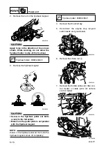
8.
Tighten the locknut, and then check the
valve clearances. Adjust if necessary.
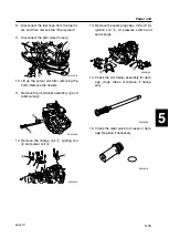
9.
Install the cylinder head cover, fuel pump,
and spark plugs.
10. Connect the fuel hoses and spark plug
caps, and then install the manual starter
and timing belt cover.
Valve clearance:
Intake
d
:
0.15–0.25 mm (0.0059–0.0098 in)
Exhaust
e
:
0.20–0.30 mm (0.0079–0.0118 in)
Locknut:
14 N·m (1.4 kgf·m, 10 ft·lb)
5
4
6D450090
b
c
6D430115
6D45F11-05 03.10.9 20:44 Page 8


