
6D45F11
5-42
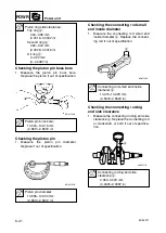
9
8
7
6
5
4
3
2
1
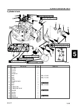
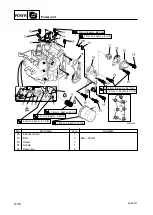
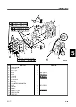
Cylinder block
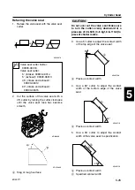
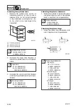
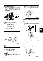
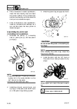
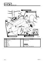
Checking the crankshaft
1.
Measure the crankshaft journal diameter
a
, crank pin diameter
b
, and crank pin
width
c
. Replace the crankshaft if out of
specification.
2.
Measure the crankshaft run-out. Replace
the crankshaft if out of specification.
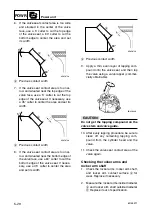
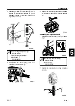
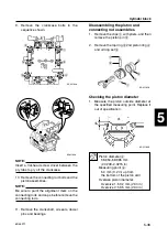
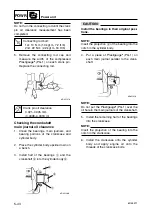
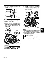
Checking the crankshaft pin oil
clearance
1.
Clean the bearings and the connecting
rod.
2.
Put a piece of Plastigauge
®
(PG-1) onto
the crank pin, parallel to the crankshaft.
NOTE:
Be sure not to put the Plastigauge
®
(PG-1)
over the oil hole in the crank pin of the crank-
shaft.
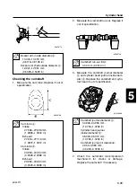
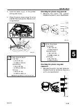
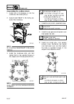
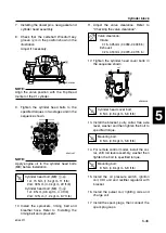
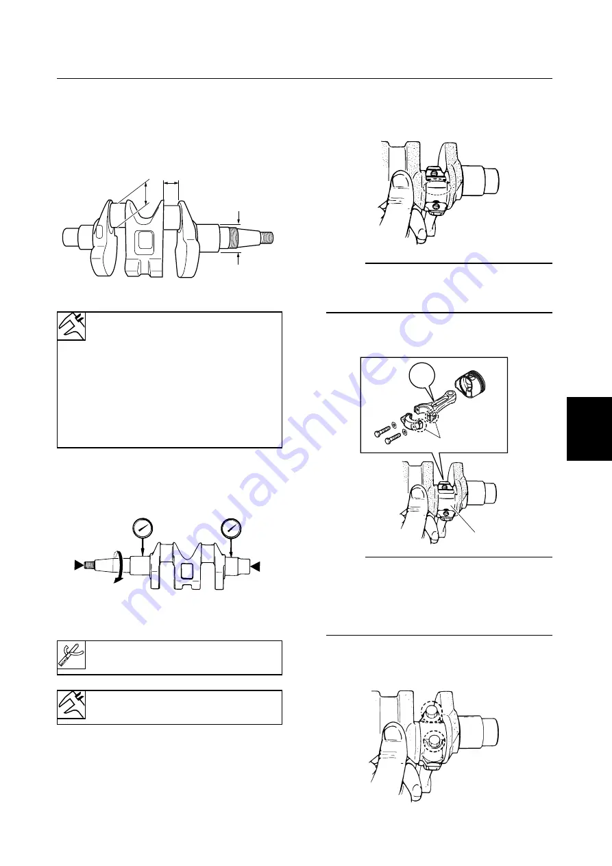
3.
Install the connecting rod to the crank pin
1
.
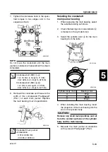
NOTE:
9
Align the finished side
a
on the connecting
rod cap and connecting rod.
9
Face the embossed “Y” mark on the con-
necting rod toward the flywheel side of the
crankshaft.
4.
Tighten the connecting rod bolts to the
specified torques in two stages.
b
c
a
6D451280
6D451290
Crankshaft journal diameter
a
:
34.997–35.009 mm
(1.3778–1.3783 in)
Crank pin diameter
b
:
30.997–31.009 mm
(1.2204–1.2208 in)
Crank pin width
c
:
21.000–21.070 mm
(0.8268–0.8295 in)
Crank stand aligner:
90890-03107
Crankshaft run-out limit:
0.05 mm (0.0020 in)
6D451340
Y
a
1
6D451350
6D451360
6D45F11-05 03.10.9 20:44 Page 45


