

6D45F11
5-4
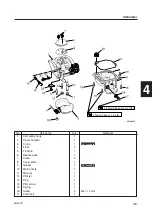
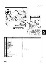
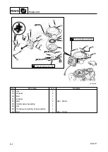
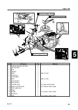
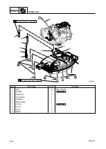
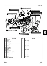
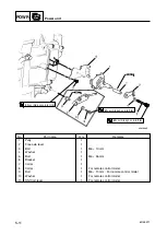
9
8
7
6
5
4
3
2
1
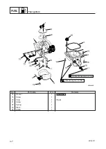
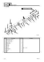
Power unit
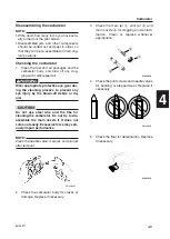
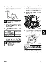
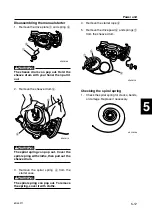
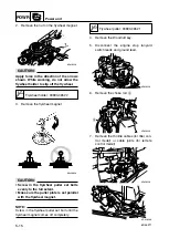
Checking the oil pressure switch
1.
Install the special service tool onto the oil
pressure switch as shown.
2.
Apply the specified pressure to oil pres-
sure switch. Check the oil pressure
switch continuity
3.
If out of specification, replace if neces-
sary.
4.
Check that the relief valve opening pres-
sure, when the engine engine speed
increased. Clean or replace if necessary.
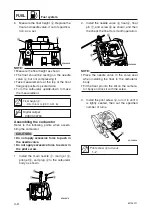
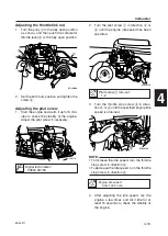
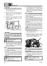
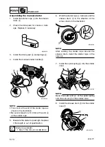
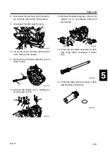
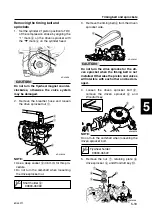
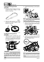
Checking the valve clearance
1.
Remove the manual starter and timing
belt cover and then disconnect the spark
plug caps
1
, spark plugs and fuel hoses.
2.
Remove the fuel pump
2
, and cylinder
head cover
3
.
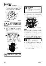
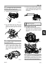
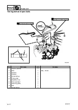
3.
Turn the flywheel clockwise and align the
“1” mark
a
on the driven sprocket with
the “
▼
” mark
b
on the cylinder head.
c
C
Do not turn the flywheel counter-clock-
wise, otherwise the valve system may be
damaged.
4.
Check the intake and exhaust valve
clearance for cylinders #1. Adjust if nec-
essary.
6D450025
b
a
6D430110
3
2
1
6D450050
Pressure
Switch continuity
14.7 kPa (0.15 kg/cm
2
,
2.13 psi) and above
No continuity
14.7 kPa (0.15 kg/cm
2
,
2.13 psi) and bellow
Continuity
Oil pressure (relief valve opening):
388.0–450.0 kpa
(3.88–4.50 kgf/cm
2
,
56.3–65.3 psi)
Vacuum/pressure pump gauge set:
90890-06756
6D45F11-05 03.10.9 20:44 Page 7


