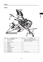
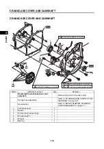


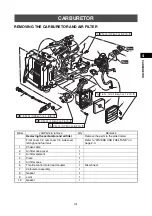


PISTON, CONNECTING ROD, CRANKSHAFT AND CRANKCASE
3-35
1
2
3
4
5
6
7
8
9
10
EN
GIN
E
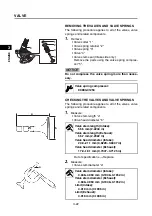
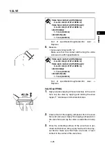
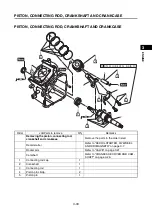
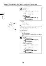
CHECKING THE CYLINDER AND PISTON
1.
Check:
• Piston wall
• Cylinder wall
Vertical scratches
Replace the cylinder, and
replace the piston and piston rings as a set.
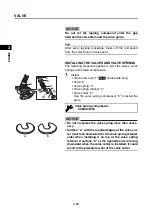
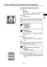
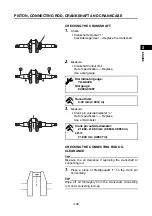
2.
Measure:
• Cylinder warpage
TIP
Measure the warpage on the contact surface of the cylin-
der at six points using the straight edge and thickness
gauge.
Out of specification
Replace the crankcase
assembly.
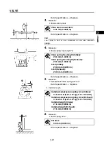
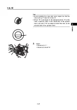
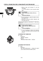
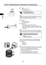
3.
Measure:
• Piston-to-cylinder clearance
a. Measure cylinder bore “C” with the cylinder bore
gauge.
TIP
Measure cylinder bore “C” by taking side-to-side and front-
to-back measurements of the cylinder.
b. If out of specification, replace the crankcase
assembly, and replace the piston and piston rings
as a set.
Feeler gauge set:
YU-26900-9
Thickness gauge:
90890-03268
Warpage limit:
0.05 mm (0.002 in)
Bore:
48.600–48.620 mm (1.9134–1.9142 in)
Wear limit:
48.620 mm (1.9142 in)
“C” = maximum of D
1
, D
2
, D
3
, D
4
, D
5
, D
6
Summary of Contents for EF2200iS
Page 2: ...7PC F8197 E0_Hyoshi indd 3 4 2019 08 28 16 31 47 ...
Page 18: ...SPECIAL TOOLS AND TESTERS 1 8 1 2 3 4 5 6 7 8 9 10 GENERAL INFORMATION MEMO ...
Page 50: ...PERIODIC MAINTENANCE 2 32 1 2 3 4 5 6 7 8 9 10 PERIODIC CHECKS AND ADJUSTMENTS MEMO ...
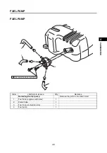
Page 99: ...FUEL PUMP 4 7 1 2 3 4 5 6 7 8 9 10 CARBURETOR MEMO ...
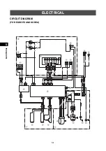
Page 116: ...ELECTRICAL COMPONENTS 5 17 1 2 3 4 5 6 7 8 9 10 ELECTRICAL MEMO ...
Page 138: ...WIRE ROUTING DIAGRAM 7 16 1 2 3 4 5 6 7 8 9 10 SPECIFICATIONS ENGINE AND GENERATOR ...
Page 140: ...WIRE ROUTING DIAGRAM 7 18 1 2 3 4 5 6 7 8 9 10 SPECIFICATIONS UPPER SIDE AND LEFT SIDE VIEW ...
Page 142: ...WIRE ROUTING DIAGRAM 7 20 1 2 3 4 5 6 7 8 9 10 SPECIFICATIONS CONTROL UNIT ...
Page 144: ...WIRE ROUTING DIAGRAM 7 22 1 2 3 4 5 6 7 8 9 10 SPECIFICATIONS GENERATOR ...
Page 148: ...WIRE ROUTING DIAGRAM 7 26 1 2 3 4 5 6 7 8 9 10 SPECIFICATIONS CARBURETOR AND AIR FILTER ...
Page 150: ...WIRE ROUTING DIAGRAM 7 28 1 2 3 4 5 6 7 8 9 10 SPECIFICATIONS FUEL TANK AND FUEL HOSES ...
Page 152: ...WIRE ROUTING DIAGRAM 7 30 1 2 3 4 5 6 7 8 9 10 SPECIFICATIONS ...
Page 160: ...MEMO ...
Page 161: ...7PC F8197 E0_Hyoshi indd 3 4 2019 08 28 16 31 47 ...


