

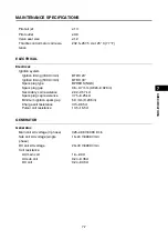
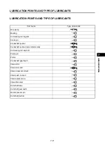


GENERAL SPECIFICATIONS
7-3
1
2
3
4
5
6
7
8
9
10
SPEC
IFICA
T
ION
S
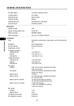
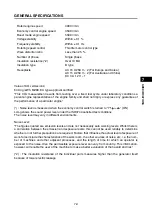
Rated engine speed
4900 r/min
Economy control engine speed
3500 r/min
Boost mode engine speed
5500 r/min
Voltage stability
Within ± 0.1 %
Frequency stability
Within ± 0.1 Hz
Rotating speed control
Throttle motor control type
Wave distortion ratio
Less than 2.5 %
Number of phase
Single phase
Insulation resistance (*2)
Over 10 M
Insulation type
B type
Receptacle
AC 16 A 250 V
2 (For Europe and Korea)
AC 15 A 250 V
2 (For Australia and China)
DC 3 A 12 V
1
******
Value of CO
2
emissions:
649.4 g/kWh, MZ80, EU type-approval certified
“This CO
2
measurement results from testing over a fixed test cycle under laboratory conditions a
parent engine representative of the engine family and shall not imply or express any guarantee of
the performance of a particular engine.”
(*) : Noise level is measured when the economy control switch is turned to “I”/“
” (ON).
L
WA
g shows the sound power level under the ISO3744 satisfied test conditions.
The noise level may vary in different environments.
Noise Level:
“The figures quoted are emission levels and are not necessarily safe working levels. Whilst there is
a correlation between the emission and exposure levels, this cannot be used reliably to determine
whether or not further precautions are required. Factors that influence the actual level of exposure of
work-force include the characteristics of the work room, the other sources of noise, etc. i.e. the num-
ber of machines and other adjacent processes, and the length of time for which an operator is
exposed to the noise. Also the permissible exposure level can vary from country. This information,
however, will enable the user of the machine to make a better evaluation of the hazard and risk.”
(*2) : The insulation resistance of the individual parts measures higher than the generator itself
because of lower electric leakage.
Summary of Contents for EF2200iS
Page 2: ...7PC F8197 E0_Hyoshi indd 3 4 2019 08 28 16 31 47 ...
Page 18: ...SPECIAL TOOLS AND TESTERS 1 8 1 2 3 4 5 6 7 8 9 10 GENERAL INFORMATION MEMO ...
Page 50: ...PERIODIC MAINTENANCE 2 32 1 2 3 4 5 6 7 8 9 10 PERIODIC CHECKS AND ADJUSTMENTS MEMO ...
Page 99: ...FUEL PUMP 4 7 1 2 3 4 5 6 7 8 9 10 CARBURETOR MEMO ...
Page 116: ...ELECTRICAL COMPONENTS 5 17 1 2 3 4 5 6 7 8 9 10 ELECTRICAL MEMO ...
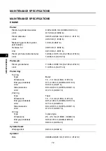
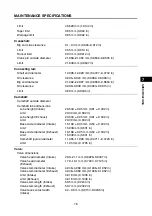
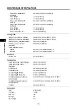
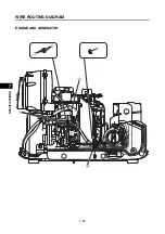
Page 138: ...WIRE ROUTING DIAGRAM 7 16 1 2 3 4 5 6 7 8 9 10 SPECIFICATIONS ENGINE AND GENERATOR ...
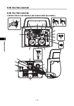
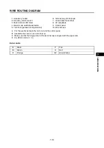
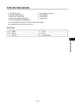
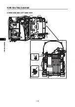
Page 140: ...WIRE ROUTING DIAGRAM 7 18 1 2 3 4 5 6 7 8 9 10 SPECIFICATIONS UPPER SIDE AND LEFT SIDE VIEW ...
Page 142: ...WIRE ROUTING DIAGRAM 7 20 1 2 3 4 5 6 7 8 9 10 SPECIFICATIONS CONTROL UNIT ...
Page 144: ...WIRE ROUTING DIAGRAM 7 22 1 2 3 4 5 6 7 8 9 10 SPECIFICATIONS GENERATOR ...
Page 148: ...WIRE ROUTING DIAGRAM 7 26 1 2 3 4 5 6 7 8 9 10 SPECIFICATIONS CARBURETOR AND AIR FILTER ...
Page 150: ...WIRE ROUTING DIAGRAM 7 28 1 2 3 4 5 6 7 8 9 10 SPECIFICATIONS FUEL TANK AND FUEL HOSES ...
Page 152: ...WIRE ROUTING DIAGRAM 7 30 1 2 3 4 5 6 7 8 9 10 SPECIFICATIONS ...
Page 160: ...MEMO ...
Page 161: ...7PC F8197 E0_Hyoshi indd 3 4 2019 08 28 16 31 47 ...


