

GENERATOR SYSTEM
6-2
1
2
3
4
5
6
7
8
9
10
TR
OUBLESHOO
TING
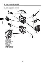
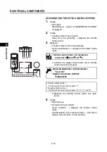
4. Wire harness
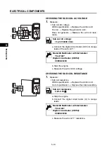
5. Main coil AC voltage
6. Main coil resistance
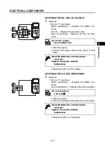
7. Sub coil AC voltage
8. Sub coil resistance
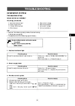
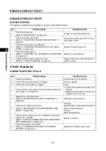
WEAK OR NO DC CURRENT
Checking procedures
TIP
• Remove the following part(s) before troubleshooting.
1) Generator assembly
• Troubleshoot with the following special tool(s).
Checking steps
Possible remedy
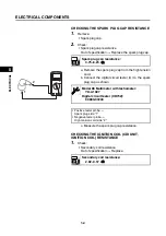
Check the terminal of the connector for contamina-
tion, rust or disconnection.
Good
Proceed to step 5.
Contamination, rust or disconnection
Connect or
replace the connector or wire harness.
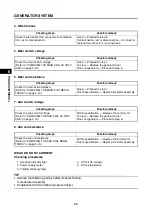
Checking steps
Possible remedy
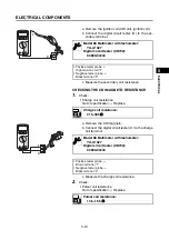
Check the main coil AC voltage.
(Refer to “CHECKING THE MAIN COIL AC VOLT-
AGE” on page 5-12.)
Good
Proceed to step 7.
Too low
Replace the generator rotor.
Does not generate
Proceed to step 6.
Checking steps
Possible remedy
Check the main coil resistance.
(Refer to “CHECKING THE MAIN COIL RESIS-
TANCE” on page 5-12.)
Good
Proceed to step 7.
Out of specification
Replace the stator assembly.
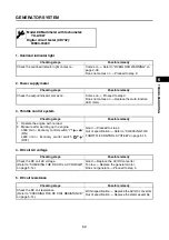
Checking steps
Possible remedy
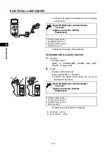
Check the sub coil AC voltage.
(Refer to “CHECKING THE SUB COIL AC VOLT-
AGE” on page 5-13.)
Within specification
Replace the control unit.
Too low
Replace the generator rotor.
Does not generate
Proceed to step 8.
Checking steps
Possible remedy
Check the sub coil resistance.
(Refer to “CHECKING THE SUB COIL RESIS-
TANCE” on page 5-13.)
Within specification
Replace the control unit.
Out of specification
Replace the stator assembly.
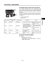
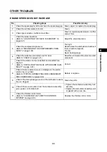
1. Overload indicator light
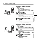
4. DC coil AC voltage
2. Power supply meter
5. DC coil resistance
3. Throttle control system
Summary of Contents for EF2200iS
Page 2: ...7PC F8197 E0_Hyoshi indd 3 4 2019 08 28 16 31 47 ...
Page 18: ...SPECIAL TOOLS AND TESTERS 1 8 1 2 3 4 5 6 7 8 9 10 GENERAL INFORMATION MEMO ...
Page 50: ...PERIODIC MAINTENANCE 2 32 1 2 3 4 5 6 7 8 9 10 PERIODIC CHECKS AND ADJUSTMENTS MEMO ...
Page 99: ...FUEL PUMP 4 7 1 2 3 4 5 6 7 8 9 10 CARBURETOR MEMO ...
Page 116: ...ELECTRICAL COMPONENTS 5 17 1 2 3 4 5 6 7 8 9 10 ELECTRICAL MEMO ...
Page 138: ...WIRE ROUTING DIAGRAM 7 16 1 2 3 4 5 6 7 8 9 10 SPECIFICATIONS ENGINE AND GENERATOR ...
Page 140: ...WIRE ROUTING DIAGRAM 7 18 1 2 3 4 5 6 7 8 9 10 SPECIFICATIONS UPPER SIDE AND LEFT SIDE VIEW ...
Page 142: ...WIRE ROUTING DIAGRAM 7 20 1 2 3 4 5 6 7 8 9 10 SPECIFICATIONS CONTROL UNIT ...
Page 144: ...WIRE ROUTING DIAGRAM 7 22 1 2 3 4 5 6 7 8 9 10 SPECIFICATIONS GENERATOR ...
Page 148: ...WIRE ROUTING DIAGRAM 7 26 1 2 3 4 5 6 7 8 9 10 SPECIFICATIONS CARBURETOR AND AIR FILTER ...
Page 150: ...WIRE ROUTING DIAGRAM 7 28 1 2 3 4 5 6 7 8 9 10 SPECIFICATIONS FUEL TANK AND FUEL HOSES ...
Page 152: ...WIRE ROUTING DIAGRAM 7 30 1 2 3 4 5 6 7 8 9 10 SPECIFICATIONS ...
Page 160: ...MEMO ...
Page 161: ...7PC F8197 E0_Hyoshi indd 3 4 2019 08 28 16 31 47 ...


