
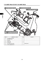
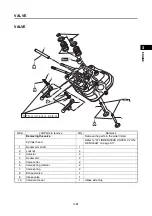


VALVE
3-23
1
2
3
4
5
6
7
8
9
10
EN
GIN
E
Out of specifications
Replace.
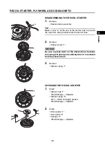
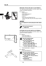
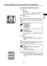
3.
Measure:
• Valve stem runout
Out of specifications
Replace.
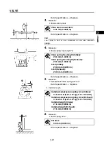
TIP
The value is half of that indicated on the dial indicator
gauge.
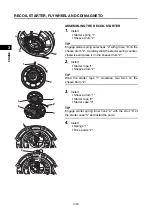
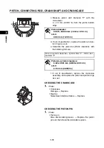
4.
Measure:
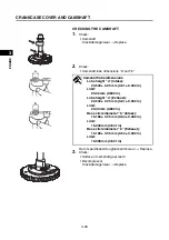
• Valve spring free length “a”
Out of specifications
Replace.
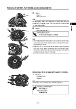
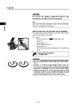
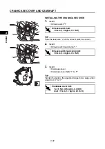
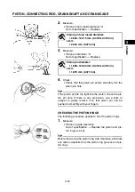
5.
Measure:
• Compressed valve spring force “a”
Out of specification
Replace.
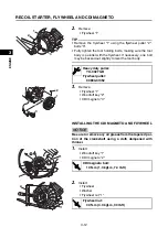
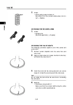
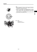
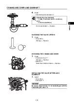
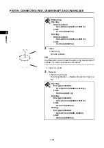
6.
Measure:
• Valve spring tilt “a”
Out of specifications
Replace.
Valve stem runout limit:
0.01 mm (0.0004 in)
a
Valve spring free length (Intake):
26.5 mm (1.0433 in)
Valve spring free length (Exhaust):
26.5 mm (1.0433 in)
Limit (Intake):
25.18 mm (0.9913 in)
Limit (Exhaust):
25.18 mm (0.9913 in)
b
a
b. Installed length
Installed compression spring force (Intake):
41.9–46.3 N (4.27–4.72 kgf, 9.41–10.40 lbf)
Installed compression spring force (Exhaust):
41.9–46.3 N (4.27–4.72 kgf, 9.41–10.40 lbf)
Installed length (Intake):
21.6 mm (0.8504 in)
Installed length (Exhaust):
21.6 mm (0.8504 in)
a
Tilt limit:
0.8 mm (0.0314 in)
Summary of Contents for EF2200iS
Page 2: ...7PC F8197 E0_Hyoshi indd 3 4 2019 08 28 16 31 47 ...
Page 18: ...SPECIAL TOOLS AND TESTERS 1 8 1 2 3 4 5 6 7 8 9 10 GENERAL INFORMATION MEMO ...
Page 50: ...PERIODIC MAINTENANCE 2 32 1 2 3 4 5 6 7 8 9 10 PERIODIC CHECKS AND ADJUSTMENTS MEMO ...
Page 99: ...FUEL PUMP 4 7 1 2 3 4 5 6 7 8 9 10 CARBURETOR MEMO ...
Page 116: ...ELECTRICAL COMPONENTS 5 17 1 2 3 4 5 6 7 8 9 10 ELECTRICAL MEMO ...
Page 138: ...WIRE ROUTING DIAGRAM 7 16 1 2 3 4 5 6 7 8 9 10 SPECIFICATIONS ENGINE AND GENERATOR ...
Page 140: ...WIRE ROUTING DIAGRAM 7 18 1 2 3 4 5 6 7 8 9 10 SPECIFICATIONS UPPER SIDE AND LEFT SIDE VIEW ...
Page 142: ...WIRE ROUTING DIAGRAM 7 20 1 2 3 4 5 6 7 8 9 10 SPECIFICATIONS CONTROL UNIT ...
Page 144: ...WIRE ROUTING DIAGRAM 7 22 1 2 3 4 5 6 7 8 9 10 SPECIFICATIONS GENERATOR ...
Page 148: ...WIRE ROUTING DIAGRAM 7 26 1 2 3 4 5 6 7 8 9 10 SPECIFICATIONS CARBURETOR AND AIR FILTER ...
Page 150: ...WIRE ROUTING DIAGRAM 7 28 1 2 3 4 5 6 7 8 9 10 SPECIFICATIONS FUEL TANK AND FUEL HOSES ...
Page 152: ...WIRE ROUTING DIAGRAM 7 30 1 2 3 4 5 6 7 8 9 10 SPECIFICATIONS ...
Page 160: ...MEMO ...
Page 161: ...7PC F8197 E0_Hyoshi indd 3 4 2019 08 28 16 31 47 ...


