
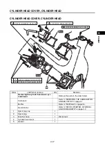
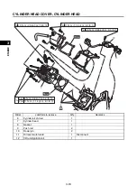
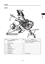

VALVE
3-26
1
2
3
4
5
6
7
8
9
10
EN
GIN
E
TIP
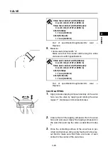
After every lapping procedure, clean off the compound
from the valve face and valve seat.
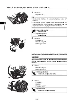
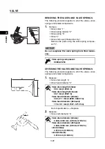
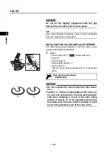
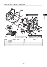
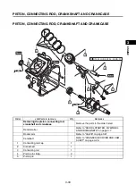
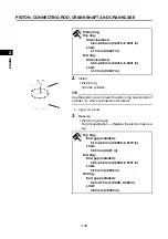
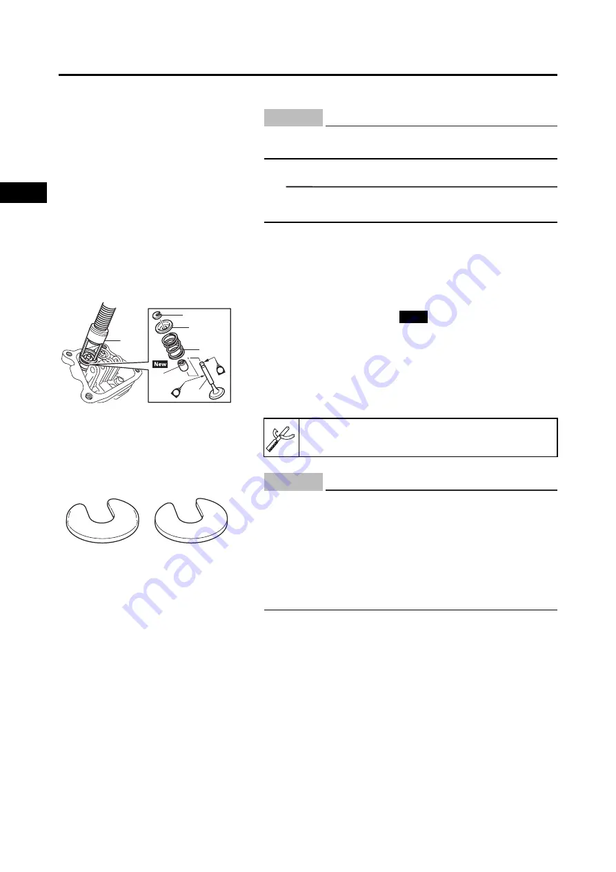
INSTALLING THE VALVES AND VALVE SPRINGS
The following procedure applies to all of the valves, valve
springs and related components.
1.
Install:
• Valve stem seal “1”
(Intake side only)
• Valve “2”
• Valve spring “3”
• Valve spring retainer “4”
• Valve cotter “5”
Use the valve spring compressor “6” to install the
parts.
Do not let the lapping compound enter the gap
between the valve stem and the valve guide.
NOTICE
1
2
3
4
5
6
E
M
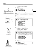
Valve spring compressor:
90890-01253
New
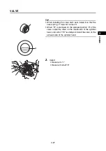
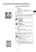
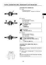
a
b
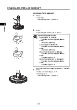
• Do not compress the valve spring more than neces-
sary.
• Surface “a” with the rounded edges of the valve cot-
ter must face downward (to the valve spring retainer
side) when installing it on top of the valve spring
retainer. If surface “b” of the opposite side is facing
downward when the valve cotter is installed, it could
result in the premature wear of the valve cotter.
NOTICE
Summary of Contents for EF2200iS
Page 2: ...7PC F8197 E0_Hyoshi indd 3 4 2019 08 28 16 31 47 ...
Page 18: ...SPECIAL TOOLS AND TESTERS 1 8 1 2 3 4 5 6 7 8 9 10 GENERAL INFORMATION MEMO ...
Page 50: ...PERIODIC MAINTENANCE 2 32 1 2 3 4 5 6 7 8 9 10 PERIODIC CHECKS AND ADJUSTMENTS MEMO ...
Page 99: ...FUEL PUMP 4 7 1 2 3 4 5 6 7 8 9 10 CARBURETOR MEMO ...
Page 116: ...ELECTRICAL COMPONENTS 5 17 1 2 3 4 5 6 7 8 9 10 ELECTRICAL MEMO ...
Page 138: ...WIRE ROUTING DIAGRAM 7 16 1 2 3 4 5 6 7 8 9 10 SPECIFICATIONS ENGINE AND GENERATOR ...
Page 140: ...WIRE ROUTING DIAGRAM 7 18 1 2 3 4 5 6 7 8 9 10 SPECIFICATIONS UPPER SIDE AND LEFT SIDE VIEW ...
Page 142: ...WIRE ROUTING DIAGRAM 7 20 1 2 3 4 5 6 7 8 9 10 SPECIFICATIONS CONTROL UNIT ...
Page 144: ...WIRE ROUTING DIAGRAM 7 22 1 2 3 4 5 6 7 8 9 10 SPECIFICATIONS GENERATOR ...
Page 148: ...WIRE ROUTING DIAGRAM 7 26 1 2 3 4 5 6 7 8 9 10 SPECIFICATIONS CARBURETOR AND AIR FILTER ...
Page 150: ...WIRE ROUTING DIAGRAM 7 28 1 2 3 4 5 6 7 8 9 10 SPECIFICATIONS FUEL TANK AND FUEL HOSES ...
Page 152: ...WIRE ROUTING DIAGRAM 7 30 1 2 3 4 5 6 7 8 9 10 SPECIFICATIONS ...
Page 160: ...MEMO ...
Page 161: ...7PC F8197 E0_Hyoshi indd 3 4 2019 08 28 16 31 47 ...


