


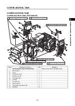
COVERS AND FUEL TANK
2-8
1
2
3
4
5
6
7
8
9
10
PERIOD
IC C
H
ECK
S
AN
D AD
JU
STMEN
T
S
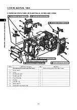
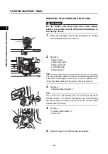
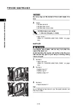
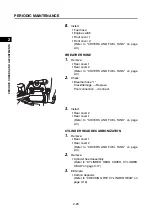
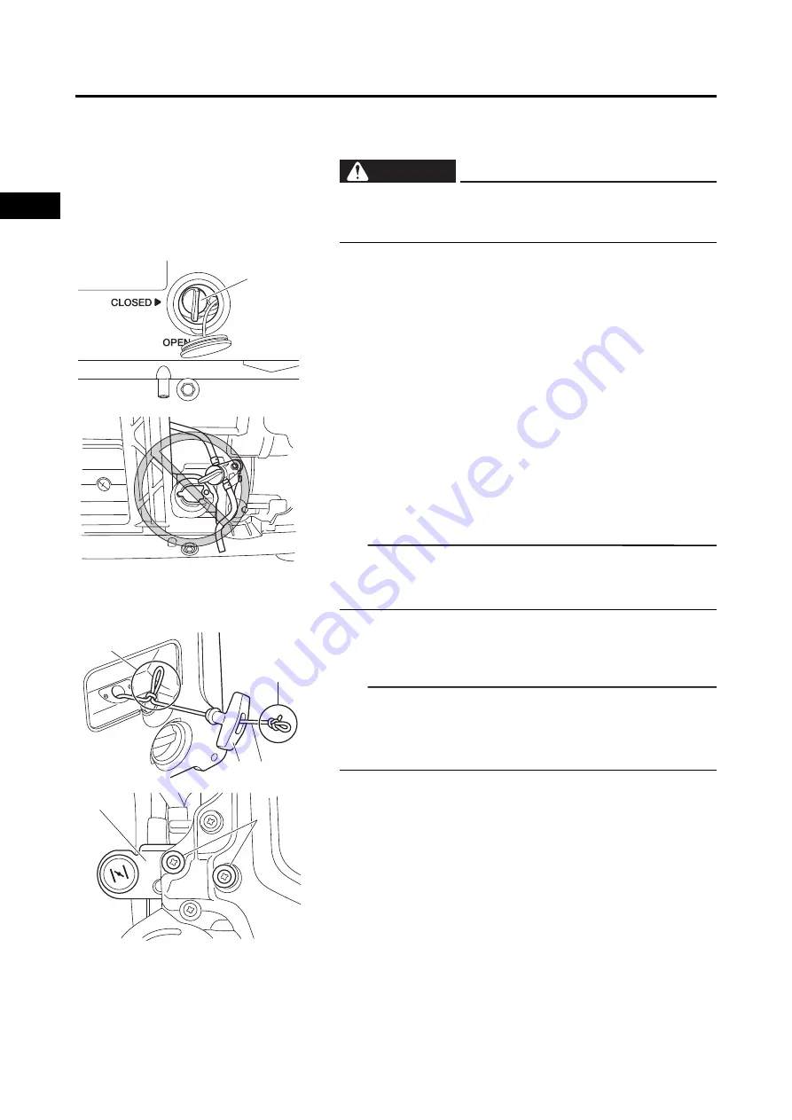
REMOVING THE COVERS AND FUEL TANK
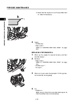
1.
Drain the remained fuel in the carburetor by turning
the carburetor fuel drain cock “1”.
2.
Remove:
• Rear cover 1
• Side cover right
• Side cover left
• Fuel tank cap
• Rear cover 2
TIP
It is not recommended to remove the carburetor fuel drain
cock when removing the rear cover 2, as it is difficult to re-
insert the drain hose into the hole of the rear cover 2.
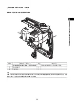
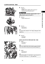
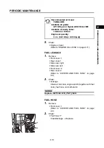
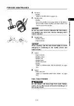
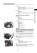
3.
Remove:
• Recoil starter handle “1”
TIP
Tie a knot “a” in the starter rope “2” in front of the recoil
starter handle “1” to prevent the starter rope from entering
the starter case, and then untie the knot “b” on the starter
handle side to remove.
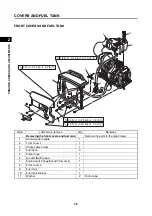
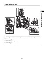
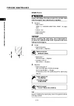
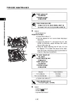
4.
Remove:
• Choke cable holder “1”
• Screw “2”
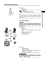
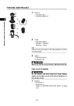
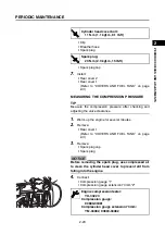
5.
Drain the fuel from the fuel tank completely.
Do not smoke, and keep away from open flames,
sparks, or any other source of fire when handling or in
the vicinity of fuel.
WARNING
1
b
1
2
a
1
2
Summary of Contents for EF2200iS
Page 2: ...7PC F8197 E0_Hyoshi indd 3 4 2019 08 28 16 31 47 ...
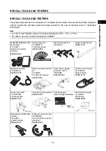
Page 18: ...SPECIAL TOOLS AND TESTERS 1 8 1 2 3 4 5 6 7 8 9 10 GENERAL INFORMATION MEMO ...
Page 50: ...PERIODIC MAINTENANCE 2 32 1 2 3 4 5 6 7 8 9 10 PERIODIC CHECKS AND ADJUSTMENTS MEMO ...
Page 99: ...FUEL PUMP 4 7 1 2 3 4 5 6 7 8 9 10 CARBURETOR MEMO ...
Page 116: ...ELECTRICAL COMPONENTS 5 17 1 2 3 4 5 6 7 8 9 10 ELECTRICAL MEMO ...
Page 138: ...WIRE ROUTING DIAGRAM 7 16 1 2 3 4 5 6 7 8 9 10 SPECIFICATIONS ENGINE AND GENERATOR ...
Page 140: ...WIRE ROUTING DIAGRAM 7 18 1 2 3 4 5 6 7 8 9 10 SPECIFICATIONS UPPER SIDE AND LEFT SIDE VIEW ...
Page 142: ...WIRE ROUTING DIAGRAM 7 20 1 2 3 4 5 6 7 8 9 10 SPECIFICATIONS CONTROL UNIT ...
Page 144: ...WIRE ROUTING DIAGRAM 7 22 1 2 3 4 5 6 7 8 9 10 SPECIFICATIONS GENERATOR ...
Page 148: ...WIRE ROUTING DIAGRAM 7 26 1 2 3 4 5 6 7 8 9 10 SPECIFICATIONS CARBURETOR AND AIR FILTER ...
Page 150: ...WIRE ROUTING DIAGRAM 7 28 1 2 3 4 5 6 7 8 9 10 SPECIFICATIONS FUEL TANK AND FUEL HOSES ...
Page 152: ...WIRE ROUTING DIAGRAM 7 30 1 2 3 4 5 6 7 8 9 10 SPECIFICATIONS ...
Page 160: ...MEMO ...
Page 161: ...7PC F8197 E0_Hyoshi indd 3 4 2019 08 28 16 31 47 ...


