
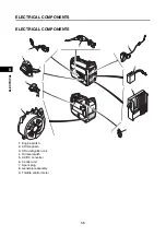

ELECTRICAL COMPONENTS
5-15
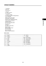
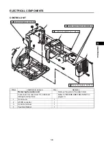
1
2
3
4
5
6
7
8
9
10
EL
E
C
TR
IC
AL
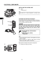
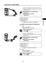
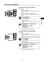
CHECKING THE THROTTLE CONTROL SYSTEM
1.
Check:
• AC output
Weak/uneven
Refer to “GENERATOR SYSTEM”
2.
Check:
• Throttle control motor rotation
Does not turns smoothly
Replace the throttle
control motor.
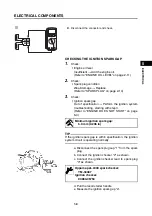
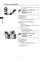
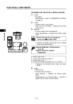
3.
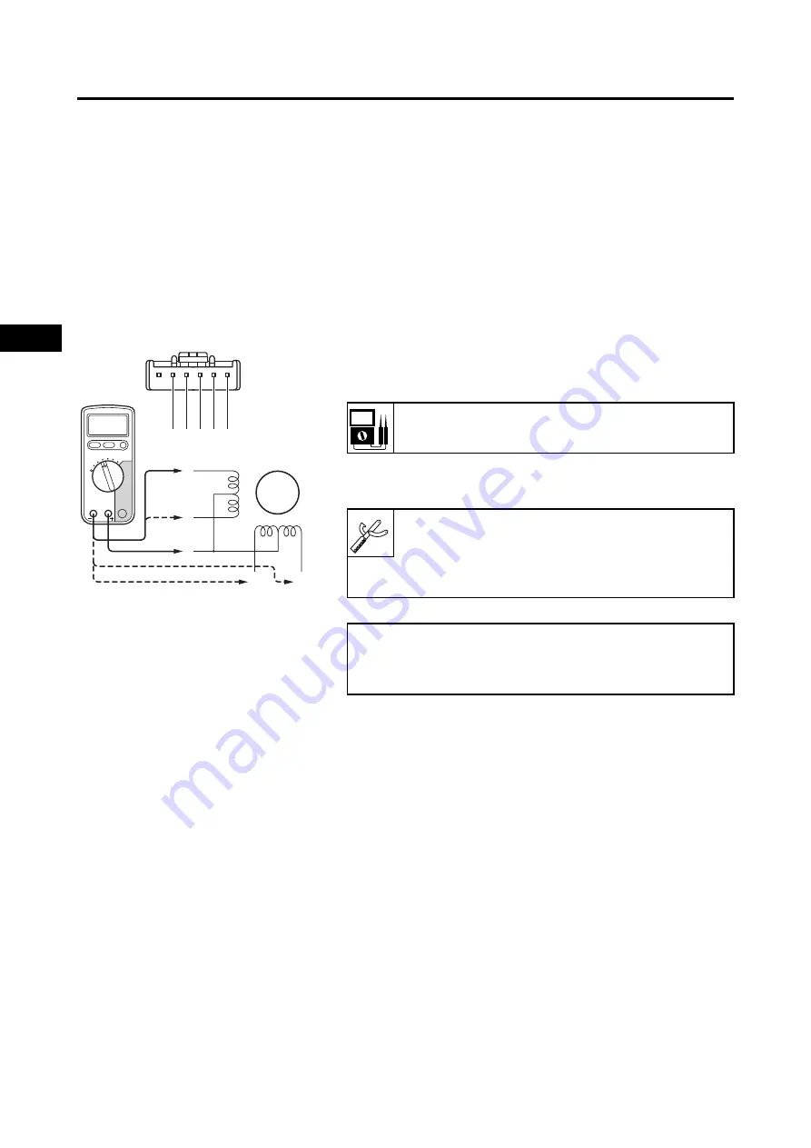
Measure:
• Throttle control motor coil resistance
Out of specification
Replace the throttle control
motor.
a. Connect the digital circuit tester (
) to throttle
control motor lead coupler.
b. Measure the throttle control motor coil resis-
tance.
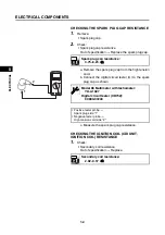
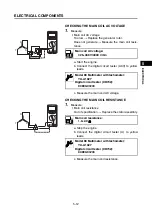
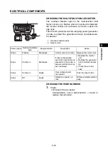
4.
Check:
• Wire harness
• Terminal of the connector
Good condition
Replace the throttle control
motor.
Contamination, rust or disconnection
Connect or
replace the connector or wire harness.
1
2
3
4
5
1
2
3
4
5
Throttle control motor coil resistance:
232.5–267.5
at 25
C (77
F)
Model 88 Multimeter with tachometer:
YU-A1927
Digital circuit tester (CD732):
90890-03243
• Positive tester probe
Throttle control motor lead coupler “1”
• Negative tester probe
Throttle control motor lead coupler “2”, “3”, “4”, and “5”.
Summary of Contents for EF2200iS
Page 2: ...7PC F8197 E0_Hyoshi indd 3 4 2019 08 28 16 31 47 ...
Page 18: ...SPECIAL TOOLS AND TESTERS 1 8 1 2 3 4 5 6 7 8 9 10 GENERAL INFORMATION MEMO ...
Page 50: ...PERIODIC MAINTENANCE 2 32 1 2 3 4 5 6 7 8 9 10 PERIODIC CHECKS AND ADJUSTMENTS MEMO ...
Page 99: ...FUEL PUMP 4 7 1 2 3 4 5 6 7 8 9 10 CARBURETOR MEMO ...
Page 116: ...ELECTRICAL COMPONENTS 5 17 1 2 3 4 5 6 7 8 9 10 ELECTRICAL MEMO ...
Page 138: ...WIRE ROUTING DIAGRAM 7 16 1 2 3 4 5 6 7 8 9 10 SPECIFICATIONS ENGINE AND GENERATOR ...
Page 140: ...WIRE ROUTING DIAGRAM 7 18 1 2 3 4 5 6 7 8 9 10 SPECIFICATIONS UPPER SIDE AND LEFT SIDE VIEW ...
Page 142: ...WIRE ROUTING DIAGRAM 7 20 1 2 3 4 5 6 7 8 9 10 SPECIFICATIONS CONTROL UNIT ...
Page 144: ...WIRE ROUTING DIAGRAM 7 22 1 2 3 4 5 6 7 8 9 10 SPECIFICATIONS GENERATOR ...
Page 148: ...WIRE ROUTING DIAGRAM 7 26 1 2 3 4 5 6 7 8 9 10 SPECIFICATIONS CARBURETOR AND AIR FILTER ...
Page 150: ...WIRE ROUTING DIAGRAM 7 28 1 2 3 4 5 6 7 8 9 10 SPECIFICATIONS FUEL TANK AND FUEL HOSES ...
Page 152: ...WIRE ROUTING DIAGRAM 7 30 1 2 3 4 5 6 7 8 9 10 SPECIFICATIONS ...
Page 160: ...MEMO ...
Page 161: ...7PC F8197 E0_Hyoshi indd 3 4 2019 08 28 16 31 47 ...


