
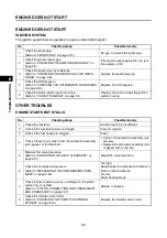


ENGINE DOES NOT START
6-4
1
2
3
4
5
6
7
8
9
10
TR
OUBLESHOO
TING
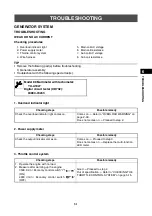
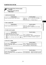
ENGINE DOES NOT START
IGNITION SYSTEM
The ignition system fails to operate (no spark or intermittent spark).
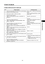
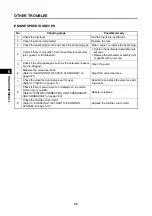
OTHER TROUBLES
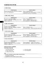
ENGINE STARTS BUT STALLS
No.
Checking steps
Possible remedy
1
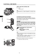
Check the spark plug.
(Refer to “SPARK PLUG” on page 2-14)
Re-gap or replace the spark plug.
2
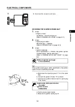
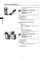
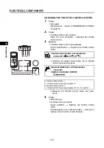
Check the ignition spark gap.
(Refer to “CHECKING THE IGNITION SPARK GAP” on
page 5-8)
If the ignition spark gap is OK, the igni-
tion system is OK.
3
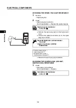
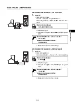
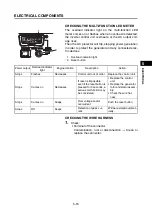
Check the spark plug cap resistance.
(Refer to “CHECKING THE SPARK PLUG CAP RESIS-
TANCE” on page 5-9)
Replace the spark plug cap.
4
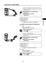
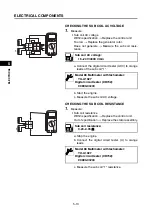
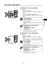
Check the CDI magneto.
(Refer to “CHECKING THE CDI MAGNETO RESISTANCE”
on page 5-10)
Replace the CDI magneto.
5
Check the entire ignition system’s wiring.
(Refer to “CIRCUIT DIAGRAM” on page 5-1)
Properly connect or repair the ignition
system’s wiring.
No.
Checking steps
Possible remedy
1
Check the fuel level.
Add the fuel if it is insufficient.
2
Check if the fuel tank strainer is clogged.
Clean or replace.
3
Check if the fuel hoses are clogged.
Clean.
4
Check if there is air suction from the carburetor assembly
joint, gasket, or throttle shaft.
• Tighten the carburetor assembly nuts
securely.
• Replace the carburetor assembly joint
or gasket with a new one.
5
Measure the valve clearance.
(Refer to “ADJUSTING THE VALVE CLEARANCE” on
page 2-21)
Adjust the valve clearance.
6
Check the compression pressure.
(Refer to “MEASURING THE COMPRESSION PRES-
SURE” on page 2-23)
Too high:
Decarbonize the combustion chamber if
there is carbon deposits.
Too low:
Next checking steps.
7
Check if there is seizure, wear, or damage on the piston,
piston ring, or cylinder.
(Refer to “PISTON, CONNECTING ROD, CRANKSHAFT
AND CRANKCASE” on page 3-33)
Rebore or replace.
8
Check the throttle control motor.
(Refer to “CHECKING THE THROTTLE CONTROL
SYSTEM” on page 5-15)
Replace the throttle control motor.
Summary of Contents for EF2200iS
Page 2: ...7PC F8197 E0_Hyoshi indd 3 4 2019 08 28 16 31 47 ...
Page 18: ...SPECIAL TOOLS AND TESTERS 1 8 1 2 3 4 5 6 7 8 9 10 GENERAL INFORMATION MEMO ...
Page 50: ...PERIODIC MAINTENANCE 2 32 1 2 3 4 5 6 7 8 9 10 PERIODIC CHECKS AND ADJUSTMENTS MEMO ...
Page 99: ...FUEL PUMP 4 7 1 2 3 4 5 6 7 8 9 10 CARBURETOR MEMO ...
Page 116: ...ELECTRICAL COMPONENTS 5 17 1 2 3 4 5 6 7 8 9 10 ELECTRICAL MEMO ...
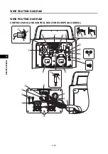
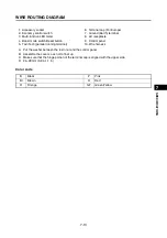
Page 138: ...WIRE ROUTING DIAGRAM 7 16 1 2 3 4 5 6 7 8 9 10 SPECIFICATIONS ENGINE AND GENERATOR ...
Page 140: ...WIRE ROUTING DIAGRAM 7 18 1 2 3 4 5 6 7 8 9 10 SPECIFICATIONS UPPER SIDE AND LEFT SIDE VIEW ...
Page 142: ...WIRE ROUTING DIAGRAM 7 20 1 2 3 4 5 6 7 8 9 10 SPECIFICATIONS CONTROL UNIT ...
Page 144: ...WIRE ROUTING DIAGRAM 7 22 1 2 3 4 5 6 7 8 9 10 SPECIFICATIONS GENERATOR ...
Page 148: ...WIRE ROUTING DIAGRAM 7 26 1 2 3 4 5 6 7 8 9 10 SPECIFICATIONS CARBURETOR AND AIR FILTER ...
Page 150: ...WIRE ROUTING DIAGRAM 7 28 1 2 3 4 5 6 7 8 9 10 SPECIFICATIONS FUEL TANK AND FUEL HOSES ...
Page 152: ...WIRE ROUTING DIAGRAM 7 30 1 2 3 4 5 6 7 8 9 10 SPECIFICATIONS ...
Page 160: ...MEMO ...
Page 161: ...7PC F8197 E0_Hyoshi indd 3 4 2019 08 28 16 31 47 ...


