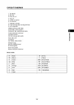
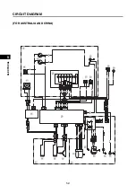

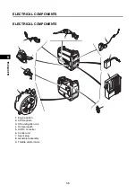
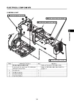
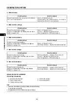
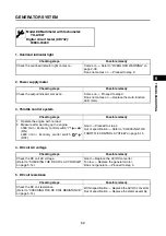
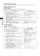
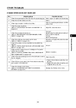


ELECTRICAL COMPONENTS
5-16
1
2
3
4
5
6
7
8
9
10
ELE
C
TRICA
L
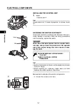
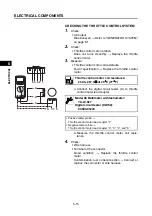
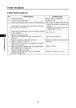
CHECKING THE MULTI-FUNCTION LED METER
The overload indicator light on the multi-function LED
meter comes on or flashes when an overload is detected,
the inverter control unit overheats, or the AC output volt-
age rises.
Then the AC protector will trip, stopping power generation
in order to protect the generator and any connected elec-
tric devices.
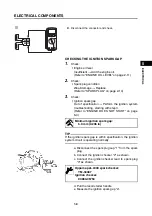
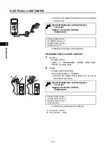
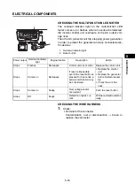
CHECKING THE WIRE HARNESS
1.
Check:
• Terminal of the connector
Contamination, rust or disconnection
Clean or
replace the connector.
1
2
1. Overload indicator light
2. Reset button
Power output
Overload indicator
light
Engine rotation
Description
Action
Stops
Flashes
Decreases
Control unit out of order.
Replace the control unit.
Stops
Comes on
Decreases
If reset is impossible
even if the reset button is
pressed for 3 seconds, a
serious malfunction may
be considered.
• Replace the control
unit.
• Replace the generator
rotor and stator assem-
bly.
• Check the wire har-
ness.
Stops
Comes on
Keeps
Over voltage and/or
overcurrent
Push the reset button.
Stops
Off
Keeps
Detection of peak cur-
rent.
Will be restored automat-
ically.
Summary of Contents for EF2200iS
Page 2: ...7PC F8197 E0_Hyoshi indd 3 4 2019 08 28 16 31 47 ...
Page 18: ...SPECIAL TOOLS AND TESTERS 1 8 1 2 3 4 5 6 7 8 9 10 GENERAL INFORMATION MEMO ...
Page 50: ...PERIODIC MAINTENANCE 2 32 1 2 3 4 5 6 7 8 9 10 PERIODIC CHECKS AND ADJUSTMENTS MEMO ...
Page 99: ...FUEL PUMP 4 7 1 2 3 4 5 6 7 8 9 10 CARBURETOR MEMO ...
Page 116: ...ELECTRICAL COMPONENTS 5 17 1 2 3 4 5 6 7 8 9 10 ELECTRICAL MEMO ...
Page 138: ...WIRE ROUTING DIAGRAM 7 16 1 2 3 4 5 6 7 8 9 10 SPECIFICATIONS ENGINE AND GENERATOR ...
Page 140: ...WIRE ROUTING DIAGRAM 7 18 1 2 3 4 5 6 7 8 9 10 SPECIFICATIONS UPPER SIDE AND LEFT SIDE VIEW ...
Page 142: ...WIRE ROUTING DIAGRAM 7 20 1 2 3 4 5 6 7 8 9 10 SPECIFICATIONS CONTROL UNIT ...
Page 144: ...WIRE ROUTING DIAGRAM 7 22 1 2 3 4 5 6 7 8 9 10 SPECIFICATIONS GENERATOR ...
Page 148: ...WIRE ROUTING DIAGRAM 7 26 1 2 3 4 5 6 7 8 9 10 SPECIFICATIONS CARBURETOR AND AIR FILTER ...
Page 150: ...WIRE ROUTING DIAGRAM 7 28 1 2 3 4 5 6 7 8 9 10 SPECIFICATIONS FUEL TANK AND FUEL HOSES ...
Page 152: ...WIRE ROUTING DIAGRAM 7 30 1 2 3 4 5 6 7 8 9 10 SPECIFICATIONS ...
Page 160: ...MEMO ...
Page 161: ...7PC F8197 E0_Hyoshi indd 3 4 2019 08 28 16 31 47 ...


