Setting the Input Channels from the Display
73
DM1000 Version 2—Owner’s Manual
6
Input Channels
E
Meters
These meters indicate the signal levels of the currently-selected Input Channel and its
available pair partner.
F
(Phase) section
You can reverse the signal phase of the currently-selected Input Channel. (See page 63
for more information.)
G
DELAY section
This section enables you to set the currently-selected channel’s Delay function. (See
page 63 for more information.)
H
PAIR section
This section indicates whether or not channels are paired. The heart icon (
) is in one
piece when channels are paired. The heart icon is broken (
) when channels are not
paired. (See page 76 for more information.)
■
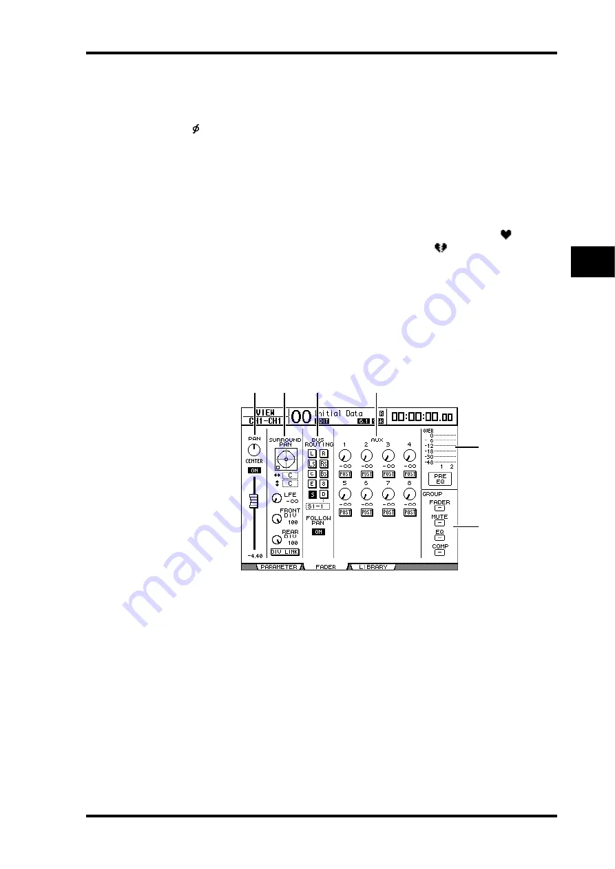
Viewing the Pan, Fader, and Aux Send Level Settings
To display the View | Fader page of a certain Input Channel, use the corresponding [SEL]
button or fader to select the desired channel, then press the DISPLAY ACCESS [VIEW] but-
ton, then the [F2] button.
Move the cursor to a parameter you wish to change, then rotate the Parameter wheel or
press the [INC]/[DEC] buttons to modify the setting.
A
PAN/ON/Fader section
•
PAN control
..................This control adjusts the currently-selected Input Channel’s Pan
parameter.
Press the [ENTER] button to reset the Pan control to Center.
•
ON/OFF button
...........This button turns on or off the currently-selected Input Chan-
nel.
•
Fader
..............................This parameter sets the fader position of the currently-selected
Input Channel. The fader knob is highlighted when the fader is
set to 0.0 dB.
Press the [ENTER] button to reset the Fader to 0.0 dB.
B
SURROUND PAN section
•
SURROUND PAN
........The Surround pan parameters for the currently-selected Input
Channel are displayed only when a Surround mode is selected.
See page 125 for more information on Surround pan.
5
6
3
2
1
4
Summary of Contents for DM 1000
Page 42: ...42 Chapter 3 Operating Basics DM1000 Version 2 Owner s Manual ...
Page 52: ...52 Chapter 4 Connections and Setup DM1000 Version 2 Owner s Manual ...
Page 92: ...92 Chapter 7 Bus Outs DM1000 Version 2 Owner s Manual ...
Page 108: ...108 Chapter 8 Aux Sends DM1000 Version 2 Owner s Manual ...
Page 146: ...146 Chapter 11 Surround Functions DM1000 Version 2 Owner s Manual ...
Page 214: ...214 Chapter 16 Automix DM1000 Version 2 Owner s Manual ...
Page 385: ...DM1000 Block Diagram ...


