220
Chapter 17—Remote Control
DM1000 Version 2—Owner’s Manual
Display
While the Pro Tools layer is selected, you can use the [F2]–[F4] buttons as well as the left
and right [
]/[
] Tab Scroll buttons to select display modes. You can select the follow-
ing display modes using these buttons:
■
Insert Display mode ( [F2] button)
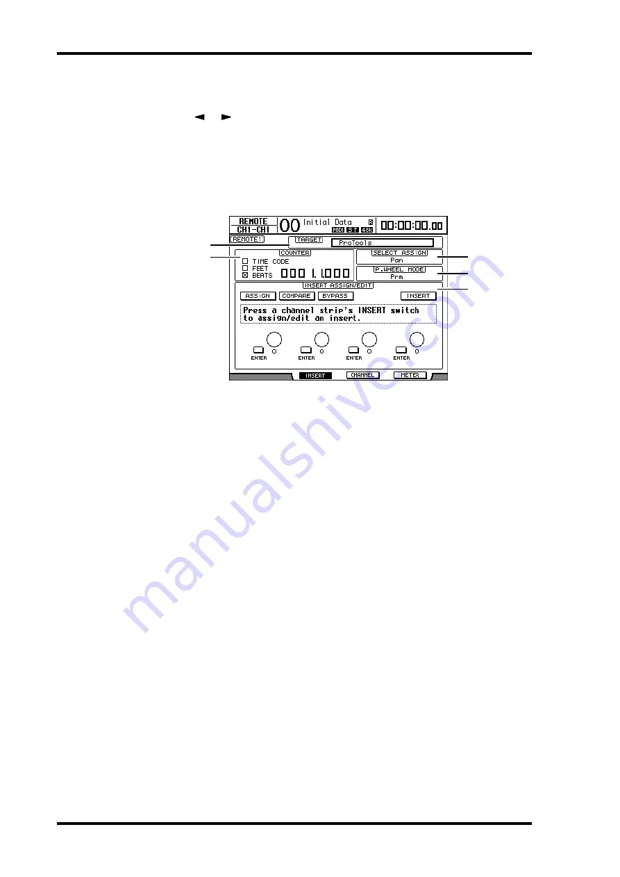
Press the [F2] button to select Insert Display mode. In this mode, you can assign and edit
plug-ins.
A
TARGET
This parameter enables you to select the remote control target device.
B
COUNTER
This counter indicates the current position. This counter works in unison with the time-
code counter on Pro Tools. The display format of the counter is specified in Pro Tools.
The following three check boxes in the COUNTER section indicate the cur-
rently-selected format.
•
TIME CODE:
................ Pro Tools timecode format is set to “Time Code.”
•
FEET:
............................. Pro Tools timecode format is set to “Feet:Frames.”
•
BEATS:
........................... Pro Tools timecode format is set to “Bars:Beats.”
•
If no check boxes are selected:
...........Pro Tools timecode format is set to “Min-
utes:Seconds” or “Samples.”
C
SELECT ASSIGN
This parameter indicates the current function of the Encoders. For example, Pan, PanR,
SndA, SndB, SndC, SndD, or SndE (see page 222).
D
P.WHEEL MODE
This parameter indicates the function currently assigned to the Parameter wheel (see
page 224).
3
4
5
2
1
Summary of Contents for DM 1000
Page 42: ...42 Chapter 3 Operating Basics DM1000 Version 2 Owner s Manual ...
Page 52: ...52 Chapter 4 Connections and Setup DM1000 Version 2 Owner s Manual ...
Page 92: ...92 Chapter 7 Bus Outs DM1000 Version 2 Owner s Manual ...
Page 108: ...108 Chapter 8 Aux Sends DM1000 Version 2 Owner s Manual ...
Page 146: ...146 Chapter 11 Surround Functions DM1000 Version 2 Owner s Manual ...
Page 214: ...214 Chapter 16 Automix DM1000 Version 2 Owner s Manual ...
Page 385: ...DM1000 Block Diagram ...


