11
TOOLS for 01X/Plug-in Effect Installation Guide
w
Latency
This determines the latency of mLAN, or how quickly the data is processed.
Latency when using mLAN
The particular configuration of your computer (processing speed, system memory size, etc.) may affect its ability to properly record and play back audio
data in your audio sequencer, resulting in noise or other audio problems. In most cases, you can solve the problem by adjusting the latency (delay time).
• A small latency value results in a short delay time and gives optimum response for real-time recording/playback.
• A large latency value results in a long delay time, but allows for use of more audio channels and plug-in effects.
The chart below shows latency values when using the mLAN ASIO Driver.
●
Transmission latency of mLAN (in playback of audio sequencer)
The total audio latency of the mLAN driver is the sum of the two values below:
(1) Basic latency value, determined by the Latency setting in the Driver Setup.
(2) Settings within the application (audio sequencer, etc.) – for example, the Preferred Buffer Size in the ASIO Control Panel.
Audio latency (msec)
(Information current as of October, 2003)
MIDI latency (msec)
• When using the mLAN ASIO Driver, open the ASIO Control Panel within the driver settings of the DAW software (the particular menu depends on the software you are using)
and set the Preferred Buffer Size as needed. When changing the Preferred Buffer Size, the latency of the ASIO driver will change from the smallest value as shown in the
chart. The total latency is the sum of the basic latency and the changed value.
• Also, when using the mLAN WDM driver, adjust as necessary the latency value of the WDM driver (which corresponds to the latency of the ASIO driver in this chart) within the
driver settings of the DAW software.
• The initial setting of the Preferred Buffer Size of the mLAN ASIO driver is the smallest value.
●
Receiving latency of mLAN (recording to audio sequencer)
The audio latency of the mLAN driver can be determined only by settings within the DAW software. (For example, twice the value of the Preferred Buffer
Size set in the ASIO mLAN Control panel becomes the actual latency value.)
●
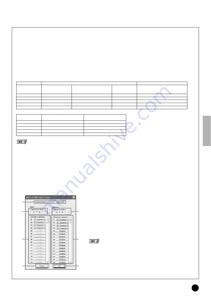
ASIO mLAN Control Panel
When you start the ASIO mLAN Control Panel, the system displays the following dialog box.
q
Preferred Buffer Size
This parameter enables you to specify the size of the buffer inside the mLAN ASIO driver.
w
Sample Size
This parameter enables you to specify the bit resolution of the audio data transmission and recep-
tion.
e
Channel Assignment
The pop-up list in the “Send” and “Receive” columns enable you to specify which mLAN audio
sequences are transmitted and received by the computer via which audio channels.
We recommend that you not change the channel assignment since this is already set by the setup
application (mLAN Auto Connector, etc.) for optimum use with mLAN devices such as the 01X. If
you’ve inadvertently changed this, reset it by manually assigning the Sequence numbers in
numerical order. This example screen shows the settings when the number of mLAN audio trans-
mission and reception channel s is set to “4CH.”
• When using the WDM + ASIO setting, you’ll need to do the following. In mLAN Driver Setup, first set
the Mode to “ASIO.” Then, after manually assigning the Sequence numbers in numerical order from
the mLAN Control Panel, go back to the mLAN Driver Setup and reset the Mode to “WDM + ASIO.”
• You can specify the sampling rate in the mLAN Driver Setup.
r
OK
Click to enable the settings and close the dialog box.
t
Cancel
Click to close the dialog box without changing the settings.
Transmission (playback; from computer to 01X)
Reception (recording; from 01X to computer)
Driver Setup settings
(basic)
Basic latency value
(with Driver Setup settings)
Settings on relevant application
(least value for Preferred Buffer Size
of mLAN ASIO Driver)
Total latency value
Settings on relevant application
(double the least value for Preferred Buffer
Size of mLAN ASIO Driver)
Very Low
2
1
3
2 (1 x 2)
Low
4
2
6
4 (2 x 2)
Medium
8
2
10
4 (2 x 2)
High
16
4
20
8 (4 x 2)
Very High
80
10
90
20 (10 x 2)
Driver Setup settings
(basic)
Transmission (from computer to 01X)
Reception (from 01X to computer)
Very Low
2
1
Low
2
1
Medium
2
1
High
4
2
Very High
8
4
q
t
w
e
r
w
e


