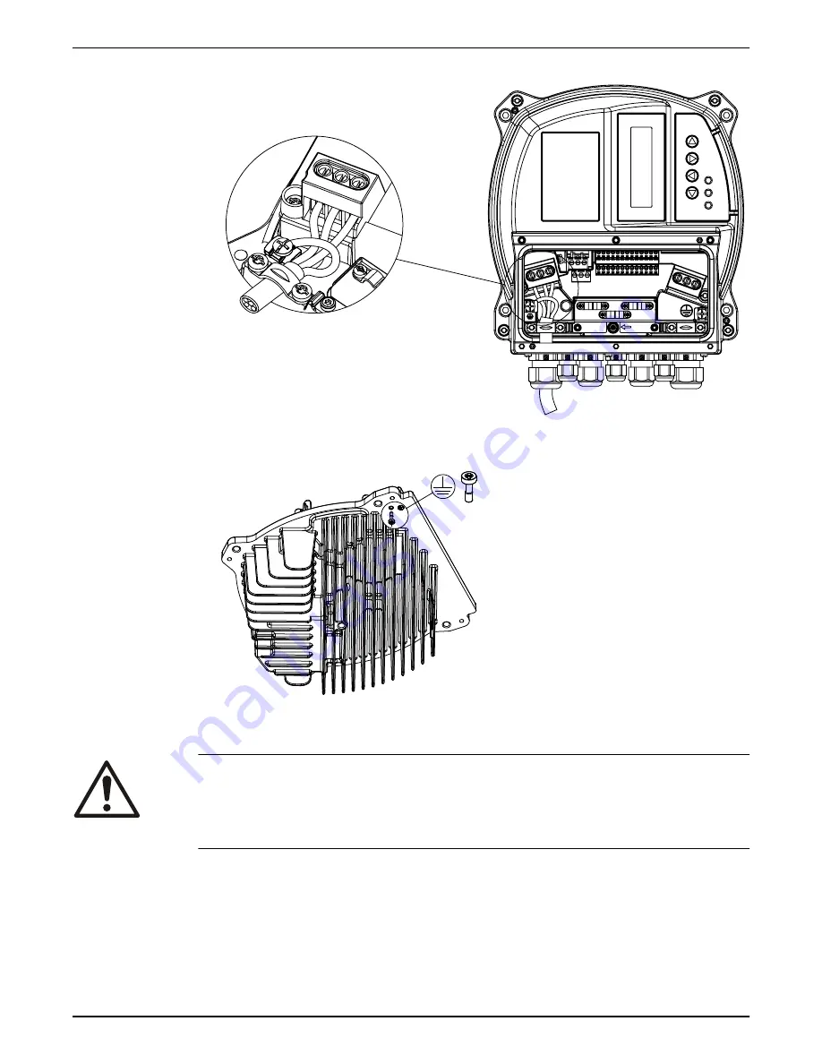
3. Connect 3–phase AC input power wiring to terminals L1, L2, and L3.
HVNG-IOM_SUPPLY-CABLE-3F_A_SC
U V
W
L1/L L2 L3/N
RFI
SWITCH
L1/L L2 L3/N
4. Ground the cable in accordance with grounding instructions provided.
5. If a double earthing is necessary, use the earth terminal under the heatsink of the drive.
HVNG-IOM_2ND_EARTHPOINT_A_SC
6.5.2 Motor connection
WARNING:
INDUCED VOLTAGE. Run output motor cables from multiple frequency converters
separately. Induced voltage from output motor cables run together can charge
equipment capacitors even with the equipment turned off and locked out. Failure to run
output motor cables separately could result in death or serious injury.
• Comply with local and national electrical codes
• Do not install power factor correction capacitors between the frequency converter and
the motor
• Do not wire a starting or pole-changing device between Hydrovar and the motor
6 Electrical Installation
HVL 2.015-4.220 Installation, Operation, and Maintenance Manual
33
Summary of Contents for hydrovar
Page 1: ...Installation Operation and Maintenance Manual HVL 2 015 4 220...
Page 2: ......
Page 114: ......
Page 115: ......


