background image


51 

  Data bits: select corresponding data bits. Default value is 8. 

  Stop bits: select corresponding stop bits. Default value is 1. 

  Parity: there are three options: odd/even/none. Default setup is none. 


Figure 4-28 

After all the setting please click save button.  
In one window display mode, right click mouse (click “Fn” Button in the front panel 
or click “Fn” key in the remote control). The interface is shown as in Figure 4-29. 


Figure 4-29 

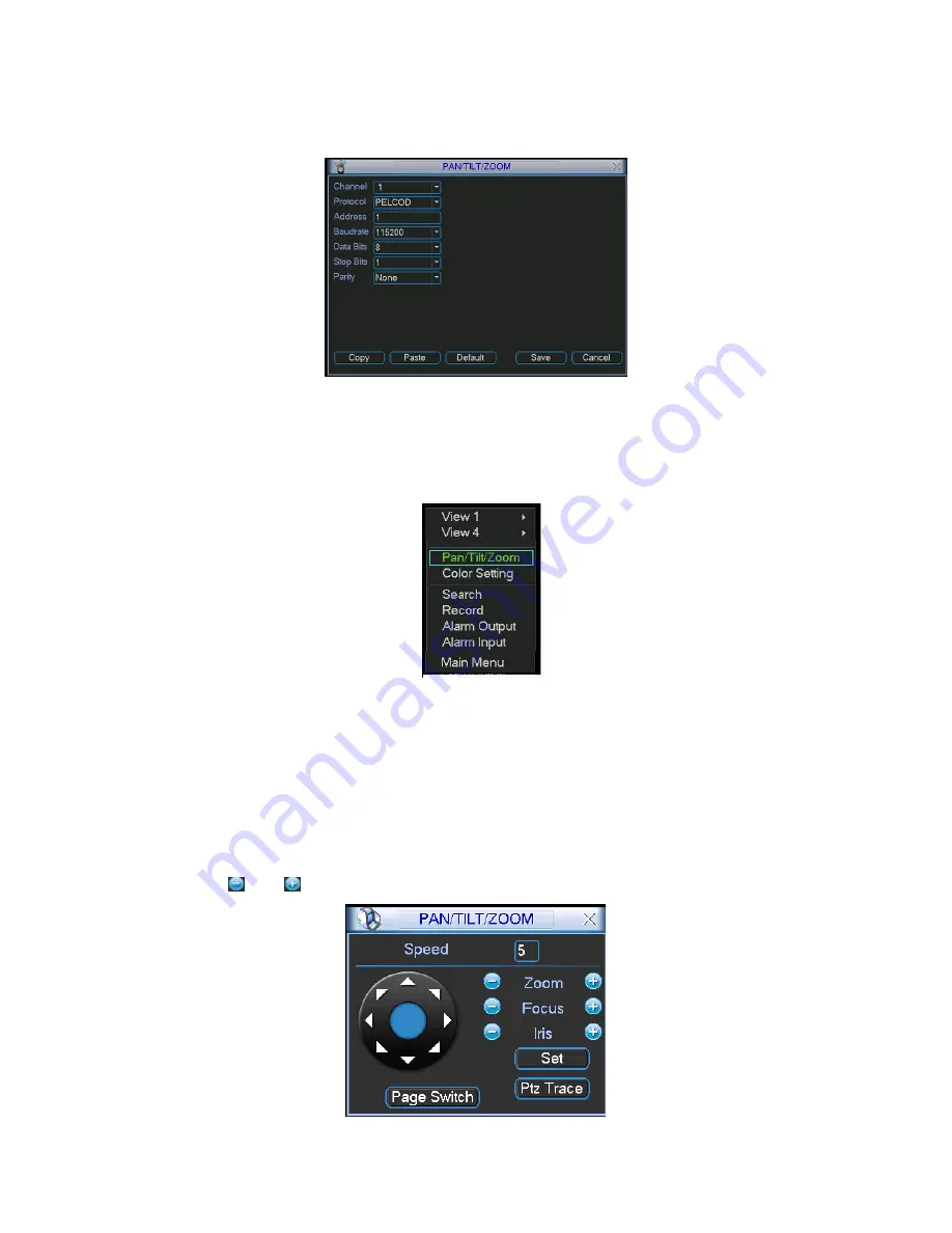
Click Pan/Tilt/Zoom, the interface is shown as below. See Figure 4-30. 
Here you can set the following items: 

  Speed: value ranges fro 1 to 8. 

  Zoom  

  Focus  

  Iris 

Click icon   and   to adjust zoom, focus and iris. 


Summary of Contents for DVR-475EL

Page 1: ...1 DVR 475EL Standalone DVR User s Manual...

Page 2: ...2 2 2 Connection Sample 17 2 3 Remote Control 18 2 4 Mouse Control 19 2 5 Virtual Keyboard Front Panel 21 2 5 1 Virtual Keyboard Input Method 21 2 5 2 Front Panel Input Method 21 3 INSTALLATION AND C...

Page 3: ...terfaces 26 3 7 1 Audio Input Audio Output 26 3 7 2 Alarm Input and Relay Output 26 3 7 3 Alarm Input 26 3 7 4 Alarm Output 27 3 7 5 Alarm Input and Output Details 27 3 7 6 Relay Output Description 29...

Page 4: ...Activation 46 4 6 1 Go to alarm setup interface 46 4 6 2 Alarm setup 46 4 7 Backup 48 4 7 1 Detect Device 48 4 7 1 Backup 48 4 8 PTZ Control and Color Setup 50 4 8 1 Cable Connection 50 4 8 2 PTZ Set...

Page 5: ...rm 69 5 3 7 Detect 69 5 3 8 Pan Tilt Zoom 69 5 3 9 Display 70 5 3 10 Default 71 5 4 Search 72 5 5 Advanced 72 5 5 1 HDD Management 73 5 5 2 Abnormity 74 5 5 3 Alarm Output 74 5 5 4 Manual Record 75 5...

Page 6: ...rol 83 6 2 5 Pattern Setup 83 6 2 6 Activate Pattern Function 84 6 2 7 Border Setup 84 6 2 8 Activate Border Function 84 6 3 Flip 84 7 WEB CLIENT OPERATION 86 7 1 Network Connection 86 7 2 Login 86 7...

Page 7: ...122 8 1 Log in 122 8 2 Enable Monitor 123 8 3 Add New Device 124 9 RS232 OPERATION 126 9 1 Network Connection 126 9 2 Keyboard 126 10 FAQ 127 APPENDIX A HDD CAPACITY CALCULATION 132 APPENDIX B COMPAT...

Page 8: ...d to be a reference tool for the installation and operation of your system Here you can find information about this series DVR features and functions as well as a detailed menu tree Before installatio...

Page 9: ...work should be done by the qualified service engineers We are not liable for any problems caused by unauthorized modifications or attempted repair 5 Environment The DVR should be installed in a cool d...

Page 10: ...devices CD RW DVD RW network download Alarm triggering screen tips buzzer PTZ preset e mail FTP upload Smart HDDs Management non working HDD hibernation HDD faulty alarm Raid function Powerful networ...

Page 11: ...SC 330 22 15 detection zones Sensitivity 1 6 level 6 is highest Trigger recording PTZ movement tour alarm e mail FTP Video Loss Trigger recording PTZ movement tour alarm e mail FTP Camera masking Trig...

Page 12: ...Interface RJ 45 Port 10 100M Network Functions TCP IP DHCP DDNS PPPoE E mail FTP Remote operation Monitor PTZ control playback system setting file download log information Auxiliary Interface USB Inte...

Page 13: ...types of front panels One series front panel is shown as in Figure 2 1 Figure 2 1 1 Upper 2 Left 3 Esc 4 Down 5 Enter 6 Right 7 Previous 8 Record 9 Slow play 10 Assistant 11 Play Pause 12 Fast forward...

Page 14: ...mode click this button to go to search interface 12 Fast forward Various fast play and normal playback Speeds In numeral input mode click this button to input 4 14 Play next I In playback mode play t...

Page 15: ...ick left right direction keys to switch between one window and multiple windows In numeral input mode Click to input 6 Increase decrease numeral In numeral input mode Click to input 7 Modify setup Swi...

Page 16: ...7 The fitst video input channel 8 The first audio input channel 9 Video output 10 Audio output 11 Network port RJ45 12 USB Port 13 VGA port 14 RS232 port 15 ALARM RS485 port 16 Fan Please refer to Fig...

Page 17: ...nnel 8 Audio output 9 Video output 10 VGA port 11 RS232 port 12 USB port 13 Networkport RJ45 14 ALARM RS485 port 15 Power button 16 Power socket 2 2 2 Connection Sample Here is a connection sample for...

Page 18: ...18 Figure 2 5 2 3 Remote Control The remote control interface is shown as in Figure 2 6...

Page 19: ...ext 13 Slow play 14 Stop 15 Fast play 16 Play Pause 2 4 Mouse Control Left click mouse System pops up password input dialogue box if you have not logged in In real time monitor mode you can go to the...

Page 20: ...keyboard directly Double left click mouse Implement special control operation such as double click one item in the file list to playback the video In multiple window mode double left click one channel...

Page 21: ...and English character small and capitalized input Move the cursor to the text column the text is shown as blue input button pops up on the right Click that button to switch between numeral input and...

Page 22: ...an use 120G 750G HDD to guarantee higher stability The formula of total HDD size is Total Capacity MB Camera Amount Recording Hours HDD Usage Per Hour M h H 264 compression is ideal for standalone DVR...

Page 23: ...data ribbon and power cord 3 3 CD DVD Burner Installation For built in burner you can dismantle front plate to install CD burner This built in burner should be set as MASTER For USB burners you need...

Page 24: ...DVR life span and other peripheral equipments operation such as cameras 3 6 Connecting Video Input and Output Devices 3 6 1 Connecting Video Input The DVR automatically detects the video standard PAL...

Page 25: ...onitor the DVR can automatically detects the monitor type And without any output device by default the DVR is configured to use a TV monitor In this case if your application requires a VGA monitor you...

Page 26: ...ideo channel on the rear panel Please refer to Figure 3 3 Figure 3 3 3 7 2 Alarm Input and Relay Output The DVR offers 4 ch alarm input for external signaling devices such as door contacts or motion d...

Page 27: ...u can use the co contactor to realize the connection between the alarm output port and the load Please refer to Figure 3 5 for more information Figure 3 5 3 7 5 Alarm Input and Output Details Please r...

Page 28: ...t it to the alarm device power below 1A A B is A cable and B cable to control 485 device You can connect them to devices such as decoder Please parallel connect a 120 resistance if there are too much...

Page 29: ...nsor to the DVR alarm input ALARM If you need to reset the touched off alarm remotely you can use DVR to supply controllable 12 V power to the alarm detector such as the smoke detector Use the same gr...

Page 30: ...1000VAC 1minute 50 60Hz between contacts with different polarity 1000VAC 1minute 50 60Hz between contact and winding 1000VAC 1minute 50 60Hz Surge voltage between contacts with same polarity 1500V 10...

Page 31: ...nd even search the record through the info The series DVR also support NKB operation You can operate the DVR from the keyboard controls instead of using the control pad on the front panel of the unit...

Page 32: ...32 Figure 3 12...

Page 33: ...ords 666666 Lower authority user who can only monitor playback backup and etc Username default Password default hidden user For your system security please modify you password after first login You ca...

Page 34: ...system can automatically backup video and resume previous working status after power failure 4 1 5 Replace Button Battery Please make sure to use the same battery model if possible We recommend repla...

Page 35: ...or record button in the remote control Manual record menu is shown as in Figure 4 5 4 2 2 2 Basic operation There are three statuses schedule manual stop Highlight icon to select corresponding channel...

Page 36: ...on light in front panel will turn on Figure 4 7 All channel manual record Please highlight ALL after Manual See Figure 4 8 When system is in manual recording all scheduled set up you have set in will...

Page 37: ...alarm recording file M motion detection recording file C card and POS test overlay recording file For some special series only There are several playback windows System supports 1 2 ch playback Figur...

Page 38: ...digital zoom You can right click mouse to exit 4 3 2 5 File backup System supports backup operation during search You can draw a before file name multiple choices Then click backup button Button 14 i...

Page 39: ...ard playback and frame by frame playback Button Illustration Remarks Backward play in playback interface In normal playback mode left click backward play button system begins backward playback Double...

Page 40: ...ard Figure 4 12 4 4 2 Basic Operation There are totally six periods See Figure 4 12 Channel Please select the channel number first You can select all if you want to set for the whole channels Week day...

Page 41: ...ly When there is file damage occurred in one disk there is a spare one in the other disk You can use this function to maintain data reliability and safety In the main menu from Setting to Schedule you...

Page 42: ...have set MD record in encode interface Main Menu Setting Schedule and schedule record in manual record interface Main Menu Advanced Manual Record Latch when motion detection complete system auto dela...

Page 43: ...Please go to chapter 5 3 9 Display for tour interval setup Snapshot System can snapshoot when alarm occurs Please highlight icon to select the corresponding function After all the setups please click...

Page 44: ...the channel you want to enable lens shading alarm Event type please select video loss Channel select the channel to record when video loss occurred Alarm output activate peripheral alarm device when...

Page 45: ...re 4 19 4 5 4 Camera Masking When someone viciously masks lens the system can alert you to guarantee video continuity Camera mask detection interface is shown as in Figure 4 20 Channel select the chan...

Page 46: ...an not copy a channel setup in video loss mode to camera mask detect mode Figure 4 20 4 6 Alarm Setup and Alarm Activation Before operation please make sure you have properly connected alarm devices s...

Page 47: ...edule interface Main Menu Setting Schedule and select schedule record in manual record interface Main Menu Advance Manual Record Latch Here is for you to set proper delay duration Value ranges from 10...

Page 48: ...as CD RW DVD driver USB backup and network download Here we introduce USB backup first You can refer to Chapter 7 Web Client Operation for network download backup operation 4 7 1 Detect Device Here is...

Page 49: ...p selected files There is a process bar for you reference When the system completes backup you can see a dialogue box prompting successful backup Figure 4 26 Click backup button system begins burning...

Page 50: ...ht be a little difference 4 8 1 Cable Connection Please follow the procedures below to go on cable connection Connect the dome RS485 port to DVR 485 port Connect dome video output cable to DVR video i...

Page 51: ...all the setting please click save button In one window display mode right click mouse click Fn Button in the front panel or click Fn key in the remote control The interface is shown as in Figure 4 29...

Page 52: ...e screen to adjust section size It can realize PTZ automatically Figure 4 32 Here is a sheet for you reference Name Function key function Shortcut key Function key function Shortcut Key Zoom Near Far...

Page 53: ...ure 4 33 click preset button and input preset number The interface is shown as in Figure 4 35 Now you can add this preset to one patrol tour Figure 4 35 4 9 2 Activate Preset In Figure 4 34 please inp...

Page 54: ...ris Go back to Figure 4 37 and click end button You can memorize all these operations as pattern 1 Figure 4 37 4 9 6 Activate Pattern Function In Figure 4 34 input mode value in the No blank and click...

Page 55: ...the auto scan button changes to stop button Click stop button to terminate scan operation 4 10 Flip In Figure 4 34 click page switch button you can see an interface is shown as below See Figure 4 39 H...

Page 56: ...ust made You need to highlight check box enable corresponding function Otherwise this function is disabled All the operations below are based on our 4 ch series DVR 5 2 Main Menu When you login the sy...

Page 57: ...tations to separate date dot beeline and solidus Snapshoot Here you can set image upload interval This function applies to some series only DST Here you can set DST time and date Please enable DST fun...

Page 58: ...y record duration Default value is 60 minutes DVR No when you are using one remote control to control several DVRs you can give a name to each DVR for your management Video standard There are two form...

Page 59: ...e Preview monitor privacy mask has two types Preview means the privacy mask zone can not be viewed by user when system is in preview status Monitor means the privacy mask zone can not be view by the u...

Page 60: ...For dual stream series DVR supports various settings for channel resolution and frame Resolution pixel PAL QCIF 176 144 CIF 352 288 HD1 352 576 2CIF 704 288 D1 704 576 NTSC QCIF 176 120 CIF 352 240 H...

Page 61: ...le resources are limited When you wan to enhance resource in one channel you need to reduce resource for other channel The system will pop up setup failure interface if the resource setup is beyond th...

Page 62: ...nt IP information Besides when PPPoE is operating you can not modify IP Subnet mask Gateway TCP port Default value is 37777 System server port 37778 is reserved for network UDP use UDP port Default va...

Page 63: ...e click current item to go to setup interface Figure 5 11 5 3 5 2 IP Filter IP filter interface is shown as in Figure 5 12 You can add IP in the following list The list supports max 64 IP addresses Pl...

Page 64: ...oup address 224 0 0 0 239 255 255 255 D address space The higher four bit of the first byte 1110 Reserved local multiple cast group address 224 0 0 0 224 0 0 255 TTL 1 When sending out telegraph For e...

Page 65: ...in the PPPoE is the DVR dynamic value You can access this IP to visit the unit Figure 5 14 5 3 5 5 NTP Setup You need to install SNTP server Such as Absolute Time Server in your PC first In Windows X...

Page 66: ...Figure 5 16 5 3 5 7 DDNS Setup DDNS setup interface is shown as in Figure 5 17 You need a PC of fixed IP in the internet and there is the DDNS software running in this PC In other words this PC is a...

Page 67: ...gure 5 18 Figure 5 18 5 3 5 9 FTP You need to download or buy FTP service tool such as Ser U FTP SERVER to establish FTP service Please install Ser U FTP SERVER first From start program Serv U FTP Ser...

Page 68: ...e folders under this FTP In Figure 5 10 select FTP and then double click mouse You can see the following interface See Figure 5 21 Figure 5 21 Please highlight the icon in front of Enable to activate...

Page 69: ...23 Figure 5 23 5 3 6 Alarm Please refer to chapter 4 6 Alarm Setup and Activation 5 3 7 Detect Please refer to chapter 4 5 Detect 5 3 8 Pan Tilt Zoom The pan tilt zoom setup includes the following ite...

Page 70: ...t when system is playback Overlay information System displays some information in the screen for your reference Display mode you can select from the dropdown list self adaptive VGA TV Enable tour acti...

Page 71: ...eed to refresh web or client end to get the latest channel name System max support 25 digital character Figure 5 26 In tour mode you can see the following interface On the right corner right click mou...

Page 72: ...e click save button system goes back to the previous menu Warning System menu color language time display mode video format IP address user account will not maintain previous setup after default opera...

Page 73: ...chedule After all the setups please click save button system needs to reboot to get all the modification activated Figure 5 30 Click alarm set button the interface is shown as below See Figure 5 31 Th...

Page 74: ...m 10s 300s System automatically delays specified seconds in turning off alarm and activated output after external alarm cancelled Show message system can pop up the message in the local screen to aler...

Page 75: ...eight bytes One name can only be used once There are four default users admin 888888 666666 and hidden user default Except user 6666 other users have administrator right Hidden user default is for sy...

Page 76: ...suitable for financial areas It supports network capture information analysis character overlay and etc According to customer s requirement there are two types with or without protocol For ATM POS fu...

Page 77: ...an see an interface is shown as in Figure 5 38 Here you can set some items such as offset length title Figure 5 38 5 6 Information Here is for you to view system information There are totally five ite...

Page 78: ...k hard disk time and system time is the same or not Please go to setting then general to modify system time At last reboot the system to solve this problem If disk is damaged system shows as Figure 5...

Page 79: ...me version information See Figure 5 43 Channel Alarm in Alarm out System version Build date Figure 5 43 5 6 5 Online Users Here is for you to manage online users See Figure 5 44 You can disconnect one...

Page 80: ...select See Figure 5 45 Logout menu user log out menu You need to input password when you login the next time Restart application reboot DVR Shutdown system shuts down and turns off power Restart syst...

Page 81: ...e 6 1 Figure 6 1 Click Pan Tilt Zoom the interface is shown as in Figure 6 2 Here you can set the following items Zoom Focus Iris Click icon and to adjust zoom focus and Iris Figure 6 2 In Figure 6 2...

Page 82: ...y function Shortcut key Function key function Shortcut key Zoom Near Far Focus Near Far Iris close Open 6 2 Preset Patrol Pattern Border Function In Figure 6 2 click the set button The interface is sh...

Page 83: ...et to one patrol number Figure 6 7 6 2 2 Activate Preset In Figure 6 6 please input preset number in the No blank and click preset button 6 2 3 Patrol Setup In Figure 6 5 click patrol button The inter...

Page 84: ...2 use direction arrows to select camera left limit and then please go to Figure 6 10 and click left limit button Repeat the above procedures to set right limit Figure 6 10 6 2 8 Activate Border Functi...

Page 85: ...85 Figure 6 11...

Page 86: ...ble user account control function Double click user account and then disable user account control After completing setup please reboot the PC System can automatically download latest web control and t...

Page 87: ...lows See Figure 7 2 Figure 7 2 After installation the interface is shown as below See Figure 7 3 Please input your user name and password Default factory name is admin and password is admin Note For s...

Page 88: ...ath Section 4 real time monitor window Please note current preview window is circled by a green rectangle zone Section 5 Here you can view window switch button You can also select video priority betwe...

Page 89: ...ns recording and this button becomes highlighted You can go to system local record to set video file path 4 Capture picture You can snapshoot important video All images are memorized in system client...

Page 90: ...ght direction keys In the middle of the eight direction keys there is a 3D intelligent positioning key Click SIT button system goes back to the single screen mode Drag the mouse in the screen to adjus...

Page 91: ...nction Zoom Near Far Focus Near Far Iris close Open Then click triangle icon in Figure 1 10 you can see the following interface See Figure 7 11 Figure 7 11 In Figure 7 11 click PTZ setup button you ca...

Page 92: ...to Figure 7 11 to implement camera operation Then you can click stop record button Now you have set one pattern 7 2 2 6 Preset In Figure 7 12 move the camera to your desired location and then input pr...

Page 93: ...htness contrast hue and saturation Current channel border becomes green Or you can click default button to use system default setup Figure 7 14 7 2 4 Picture Path and Record Path Click more button in...

Page 94: ...nterface Switch Put your mouse on the PTZ control bar until you see the following icon See Figure 7 18 Figure 7 18 Left click your mouse and then drag it to the channel control status bar You can see...

Page 95: ...e In the main window click config button you can see an interface is shown as in Figure 7 20 Figure 7 20 7 3 1 System Information Click device configuration button you can see the following interface...

Page 96: ...ersion Click version button you can see corresponding HDD information for your reference See Figure 7 22 Figure 7 22 HDD Information Here you can view HDD amount HDD status total volume and free space...

Page 97: ...97 Figure 7 23 Log Click log button you can see an interface is shown as in Figure 7 24 Here you can view current device log information Figure 7 24 7 3 2 Setting...

Page 98: ...you can select data format from the dropdown list Data separator Please select separator such as or Time format there are two options 24 H and 12 H HDD full there are two options stop recording or ov...

Page 99: ...m AV enable Video Audio System only displays video by default You need to manually enable audio function Bit rate There are two options CBR and VBR You can only set video quality in VBR mode Frame rat...

Page 100: ...alarm record A Channel select the channel number you desire Week you can select from the dropdown list Or you can select at the bottom of the interface Prerecord system can record the three to five s...

Page 101: ...igure 7 27 Figure 7 28 Tip After you finished setup for one channel you can click save as button system pops up the following interface See Figure 7 29 Now you can copy one channel setup to other chan...

Page 102: ...TTP port default setup is 80 Transfer here you can select the priority between fluency video quality Enable PPPoE In remote item enable PPPoE function and then input PPPoE name and PPPoE password you...

Page 103: ...er IP DDNServer default htm for example input http 10 5 2 149 DDNServer default htm you open a DDNS server web page Figure 7 31 RS232 RS232 includes the following items See Figure 7 32 Function There...

Page 104: ...104 Figure 7 32 Mul DDNS Here you can select DDNS type This operation needs DVR device supported See Figure 7 33 Figure 7 33 FTP...

Page 105: ...le If the file is larger than the setup value system only uploads the setup value data and ignores the rest data Interval for one channel of the same record type if there is more than one alarm system...

Page 106: ...o select alarm record in DVR schedule interface and enable schedule function in manual record interface Alarm output select alarm activation channel when alarm occurs Please note channel 3 is to contr...

Page 107: ...ame from the dropdown list Type There are three types motion detection Video loss Camera mask detection Record channel Here you can select record channel Multiple choices Please make sure you have set...

Page 108: ...se you can go to full screen display mode Do remember clicking OK button in Figure 7 41 to save your motion detection zone setup Alarm output Here you can select activated external peripheral device w...

Page 109: ...109 Figure 7 39 Figure 7 40 Figure 7 41...

Page 110: ...ing dome protocol such as Pelco Address Set corresponding dome address Default value is 1 Please note your setup here shall comply with your dome address otherwise you can not control the speed dome B...

Page 111: ...nfig button you can load a setup file Figure 7 44 Figure 7 45 7 3 2 1 Advanced Advanced includes the following items See Figure 7 46 Account HDD management Alarm input Alarm output Auto maintain Video...

Page 112: ...112 Figure 7 46 Click add group button you can see the following interface See Figure 7 47 Here you can add one new group and then select corresponding rights for the whole group accounts...

Page 113: ...ser button you can see the following interface See Figure 7 48 Here you can input a new user and then select corresponding rights Please note one user must belong to one group and user right shall not...

Page 114: ...n not support large overload It shall be less than 1A Too heavy current may result in relay damage Please use contactor if necessary Figure 7 49 HDD management This function needs DVR device supported...

Page 115: ...115 Figure 7 50 Auto maintenance Auto maintenance interface is shown as in Figure 7 51 Here you can enable auto reboot or auto delete old files function Need DVR supported Figure 7 51 Video Matrix...

Page 116: ...x interface is shown as in Figure 7 52 Please note this function needs DVR supported Figure 7 52 Snap Picture Snapshoot interface is shown as in Figure 7 53 Please note this function needs DVR support...

Page 117: ...use page up down key to view the search results Double click file name you can view the file and system will automatically backup the image in you installation directory Figure 7 54 In the search res...

Page 118: ...d button System pops up a dialogue box asking you specify directory See Figure 7 56 Figure 7 56 Then you can input file name and click save to backup file in your local pc During the download process...

Page 119: ...119 Figure 7 57 7 5 Alarm Here you can set alarm type and alarm prompt audio file See Figure 7 58 Figure 7 58 7 6 About Click about button you can view current web client information See Figure 7 59...

Page 120: ...o log in interface See Figure 7 60 Figure 7 60 7 8 Un install Web Control You can use web un install tool uninstall web bat to un install web control Please note before you un installation please clos...

Page 121: ...121...

Page 122: ...use the system you can see the following interface See Figure 8 1 Figure 8 1 After selecting a language you can see the following interface Here you can input user name and password to log in you sel...

Page 123: ...or After successfully logged in please select the device and then click connect disconnect button Select the channel you wan to view click connect disconnect button again Section 1 Section 2 Section 3...

Page 124: ...se note system only supports one window in full screen Here we recommend resolution 1024 768 Select a device name and then click connect disconnect button you can connect current device to network You...

Page 125: ...125 Figure 8 5 Add device Add organization structure...

Page 126: ...Keyboard Control keyboard is very convenient for multi DVR control menu options and PTZ control Select keyboard control from system setting RS232 function and then set concerning attributes such as pr...

Page 127: ...ment is too harsh too much dust Hardware malfunction 3 System can not detect hard disk There are following possibilities HDD is broken HDD ribbon is damaged HDD cable connection is loose 4 There is no...

Page 128: ...power picker It is not a power acoustics Audio cable is damaged DVR hardware malfunctions 9 There is audio when monitor but there is no audio when system playback There are following possibilities Set...

Page 129: ...with Windows VISTA control ActiveX control has been disabled No dx8 1 or higher Please upgrade display card driver Network connection error Network setup error Password or user name is invalid Client...

Page 130: ...is not correct Some program versions may have this problem Please upgrade your system 19 Alarm function is null There are following possibilities Alarm setup is not correct Alarm cable connection is...

Page 131: ...e or ffdshow 2004 1012 exe in Windows XP OS 23 Forget local menu operation password or network password Please contact your local service engineer or our sales person for help We can guide you to solv...

Page 132: ...capacity i m which is storage of each channel needed unit Mbyte i m i q i h i D 2 In the formula i h means the recording time for each day hour i D means number of days for which the video shall be k...

Page 133: ...uzer Freedom 1G Sandisk Cruzer Freedom 2G Kingston DataTraveler 1G Kingston DataTraveler 2G Kingston DataTraveler 1G Kingston DataTraveler 2G Maxell USB Flash Stick 128M Maxell USB Flash Stick 256M Ma...

Page 134: ...nterface Type Sony DRU 835A IDE DVD RW Sony DW Q120A IDE DVD RW Sony DW G120A IDE DVD RW Sony CRX 230AE IDE CD RW Sony CRX 320A IDE CD RW Sony CRX 225E IDE CD RW BenQ DW2000 IDE DVD RW BenQ DW1670 IDE...

Page 135: ...T3750330AS 750G SATA Seagate Barracuda 11 ST3500320AS 500G SATA Maxtor DiamondMax 20 STM3320820AS 320G SATA Maxtor DiamondMax 20 STM3250820AS 250G SATA Maxtor DiamondMax 21 STM3160211AS 160G SATA Maxt...

Reviews: