42
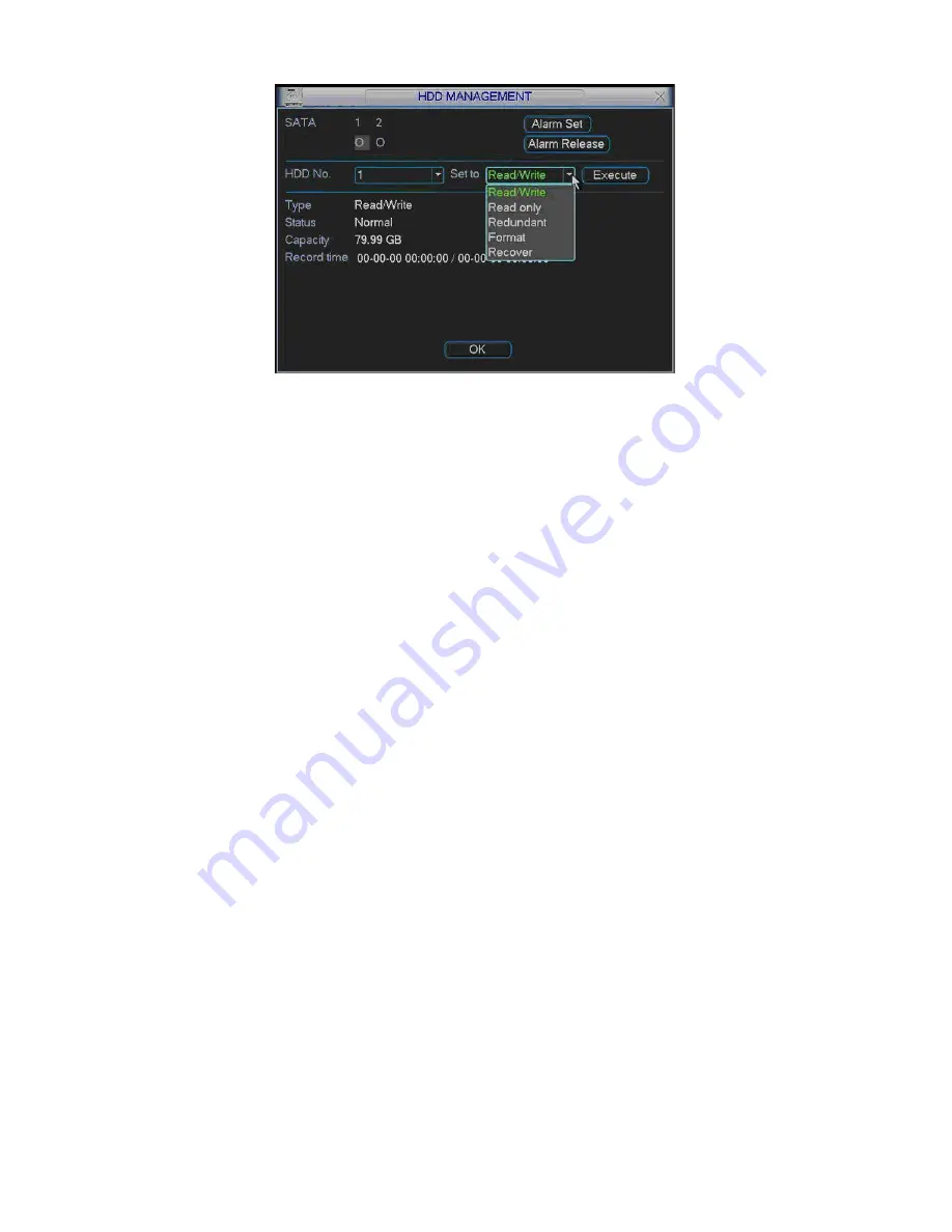
Figure 4-13
Playback or search in the redundant disk.
There are two ways for you to playback or search in the redundant disk.
Set redundant disk(s) as read-only disk or read-write disk (Main menu-
>Advanced->HDD management). See Figure 4-13.System needs to reboot to get
setup activated. Now you can search or playback file in redundant disk.
Dismantle the disk and play it in another PC.
4.5
Motion Detect
4.5.1
Go to Motion Detect Menu
In the main menu, from Setting to Detect, you can see motion detect interface.
See Figure 4-14.
4.5.2
Motion Detect
Detection menu is shown as below. See Figure 4-14.
Channel: select the channel you want to implement motion detection.
Event type: from the dropdown list you can select motion detection type.
Channel: select the channel to activate recording function once alarm occurred.
Please make sure you have set MD record in encode interface(Main Menu-
>Setting->Schedule) and schedule record in manual record interface(Main Menu-
>Advanced->Manual Record)
Latch: when motion detection complete, system auto delays detecting for a
specified time. The value ranges from 10-300(Unit: second)
Region: Click select button, the interface is shown as in Figure 4-15.Here you can
set motion detection zone. There are 396(PAL)/330(NTSC) small zones.
Sensitivity: System supports 6 levels. The sixth level has the highest sensitivity.
Show message: System can pop up a message to alarm you in the local host
screen if you enabled this function.
Send email: System can send out email to alert you when alarm occurs.
PTZ activation: Here you can set PTZ movement when alarm occurs. Such as go
to preset, tour &pattern when there is an alarm. Click
“
select
”
button, you can see
an interface is shown as in Figure 4-16.
Period: Click set button, you can see an interface is shown as in Figure 4-17.
Here you can set for business day and non-business day. In Figure 4-17, click set
Summary of Contents for DVR-475EL
Page 1: ...1 DVR 475EL Standalone DVR User s Manual...
Page 18: ...18 Figure 2 5 2 3 Remote Control The remote control interface is shown as in Figure 2 6...
Page 32: ...32 Figure 3 12...
Page 85: ...85 Figure 6 11...
Page 109: ...109 Figure 7 39 Figure 7 40 Figure 7 41...
Page 121: ...121...
Page 125: ...125 Figure 8 5 Add device Add organization structure...


