45
PTZ activation: Here you can set PTZ movement when alarm occurs. Such as go
to preset, tour & pattern when there is an alarm. Click
“
select
”
button, you can
see an interface is shown as in Figure 4-16.
Period: Click set button, you can see an interface is shown as in Figure 4-17.
Here you can set for business day and non-business day. In Figure 4-17, click set
button, you can see an interface is shown as in Figure 4-18. Here you can set
your own setup for business day and non-business day.
Sensitivity: there are six levels. The sixth level has the highest sensitivity.
Alarm output: when alarm occurred, system enables peripheral alarm devices.
Tour; Here you can enable tour function when alarm occurs. It is a one-window
tour. Please go to chapter 5.3.9 Display for tour interval setup.
Snapshot: System can snapshoot when alarm occurs.
Figure 4-19
4.5.
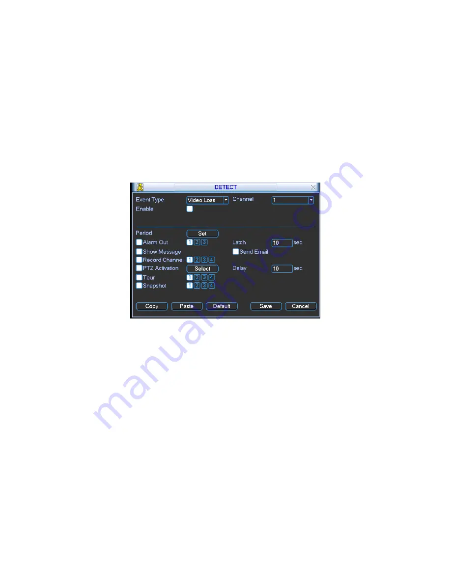
4 Camera Masking
When someone viciously masks lens, the system can alert you to guarantee video
continuity. Camera mask detection interface is shown as in Figure 4-20.
Channel: select the channel you want to enable camera mask detection function.
Event type: please select camera mask detect from the dropdown list.
Channel: select the channel to record when camera mask occurred.
Alarm output: activate peripheral alarm device when camera mask occurred.
Enable tour: Here is for you to activate tour between different cameras.
Latch: when motion detection complete, system auto delays detecting for a
specified time. The value ranges from 10-300(Unit: second)
Show message: System can pop up a message to alarm you in the local host
screen if you enabled this function.
Send email: System can send out email to alert you when alarm occurs.
PTZ activation: Here you can set PTZ movement when alarm occurs. Such as go
to preset, tour &pattern when there is an alarm. Click
“
select
”
button, you can see
an interface is shown as in Figure 4-16.
Summary of Contents for DVR-475EL
Page 1: ...1 DVR 475EL Standalone DVR User s Manual...
Page 18: ...18 Figure 2 5 2 3 Remote Control The remote control interface is shown as in Figure 2 6...
Page 32: ...32 Figure 3 12...
Page 85: ...85 Figure 6 11...
Page 109: ...109 Figure 7 39 Figure 7 40 Figure 7 41...
Page 121: ...121...
Page 125: ...125 Figure 8 5 Add device Add organization structure...


