6 / 99
www.xovis.com
2
Installation Fundamentals
Network requirements
The device needs to be connected to the network by a shielded Cat 5 RJ45 Cable. The plug
and the sensor need to be free from any mechanical pressure. The sensor supports Ethernet
10/100Mb Full/Half/Auto negotiation based on the IEEE 802.3 standard. It is highly
recommended to set the switch port to auto negotiation.
Power over Ethernet
The sensor is powered by PoE Class 0 compliant to IEEE 802.3af. As defined by the standard,
the network switch port needs to provide 15 Watts at 48 V.
Sensor LED
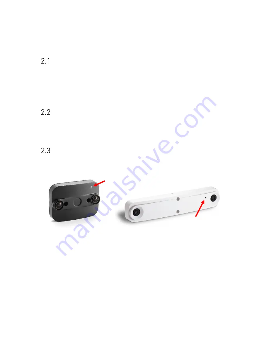
The PC-Series sensor provides a multifunctional LED on the front side. The red arrow on the
next picture indicate the LED on the PC2 and PC3 models.
Figure 2: PC2 LED (left) and PC3 LED (right)
The LED indicates the following states:
-
Green: Device is powered by PoE
-
Orange/Green blinking: Device is up and running
The LED state can be useful during installation. When using the optional housing, the LED
will be covered after successful mounting.
Summary of Contents for PC Series
Page 1: ...PC Series User manual...


