VC707 Evaluation Board
65
UG885 (v1.2) February 1, 2013
Feature Descriptions
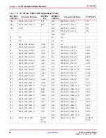
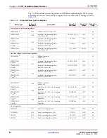
Power Management
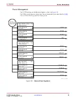
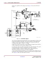
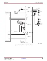
The VC707 board power distribution diagram is shown in
.
The PCB layout and power system meet the recommended criteria described in
,
7 Series FPGAs PCB Design and Pin Planning Guide
.
X-Ref Target - Figure 1-33
Figure 1-33:
Onboard Power Regulators
UG
88
5_c1_
3
0_0
3
2412
VCCAUX
VCC
3
V
3
VADJ
VCC2V5
VCC1V5
MGTAVTT
VCC12_P
Power Pl
a
ne
From
S
W12
MGTAVCC
VCCINT
VCCAUX_IO
VCCBRAM
MGTVCCAUX
Power Controller 2 (A
u
x)
PMB
us
Addre
ss
5
3
S
witching Reg
u
l
a
tor
1.5V
a
t 10A
U21
S
witching Reg
u
l
a
tor
2.5V
a
t 10A
S
witching Reg
u
l
a
tor
1.2V
a
t 10A
U22
S
witching Reg
u
l
a
tor
1.0V
a
t 10A
Power Controller
3
PMB
us
Addre
ss
54
S
witching Reg
u
l
a
tor
1.0V
a
t 10A
U62
S
witching Reg
u
l
a
tor
2.0V
a
t 10A
S
witching Reg
u
l
a
tor
0V -
3
.
3
V
a
t 10A
U12
S
witching Reg
u
l
a
tor
1.0V
a
t 20A
U25
Power Controller 1 (Core)
PMB
us
Addre
ss
52
S
witching Reg
u
l
a
tor
3
.
3
V
a
t 10A
U20
S
witching Reg
u
l
a
tor
1.
8
V
a
t 20A
U42
U4
3
U64
S
witching Reg
u
l
a
tor
1.
8
V
a
t 10A
U6
3
S
witching Reg
u
l
a
tor
1.
8
V
a
t 10A
VCC1V
8

