26
VC707 Evaluation Board
UG885 (v1.2) February 1, 2013
Chapter 1:
VC707 Evaluation Board Features
Note:
In
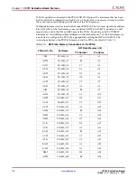
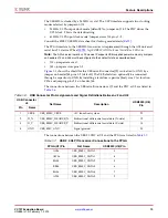
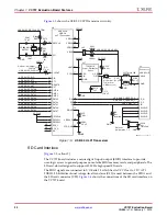
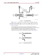
, USER_CLOCK_N and USER_CLOCK_P are differential clock signals.
User SMA Clock (USER_SMA_CLOCK_P and USER_SMA_CLOCK_N)
[
, callout
]
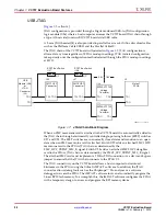
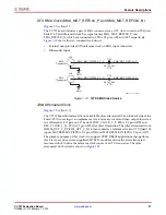
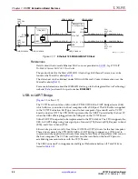
An external high-precision clock signal can be provided to the FPGA bank 14 by
connecting differential clock signals through the onboard 50
Ω
SMA connectors J31 (P) and
J32 (N). The differential clock signal names are USER_SMA_CLOCK_P and
USER_SMA_CLOCK_N, which are connected to FPGA U1 pins AJ32 and AK32
respectively. The user-provided 1.8 V differential clock circuit is shown in
X-Ref Target - Figure 1-10
Figure 1-10:
User Clock Source
UG885_c1_10_021412
GND
VCC3V3
Si570
Programmable
Oscillator
NC
OE
GND
SCL
SDA
VDD
1
2
3
8
7
6
U34
R15
4.7K
Ω
5%
USER CLOCK N
C192
0.01
μ
F 25V
X7R
CLK-
4
5
GND
VCC3V3
CLK+
USER CLOCK P
USER CLOCK SDA
USER CLOCK SCL
10 MHz - 810 MHz
50 PPM
To I2C
Bus Switch
(U52)
X-Ref Target - Figure 1-11
Figure 1-11:
User SMA Clock Source
USER_SMA_CLOCK_P
J32
USER_SMA_CLOCK_N
GND
J31
GND
UG885_c1_11_020612
SMA
Connector
SMA
Connector

