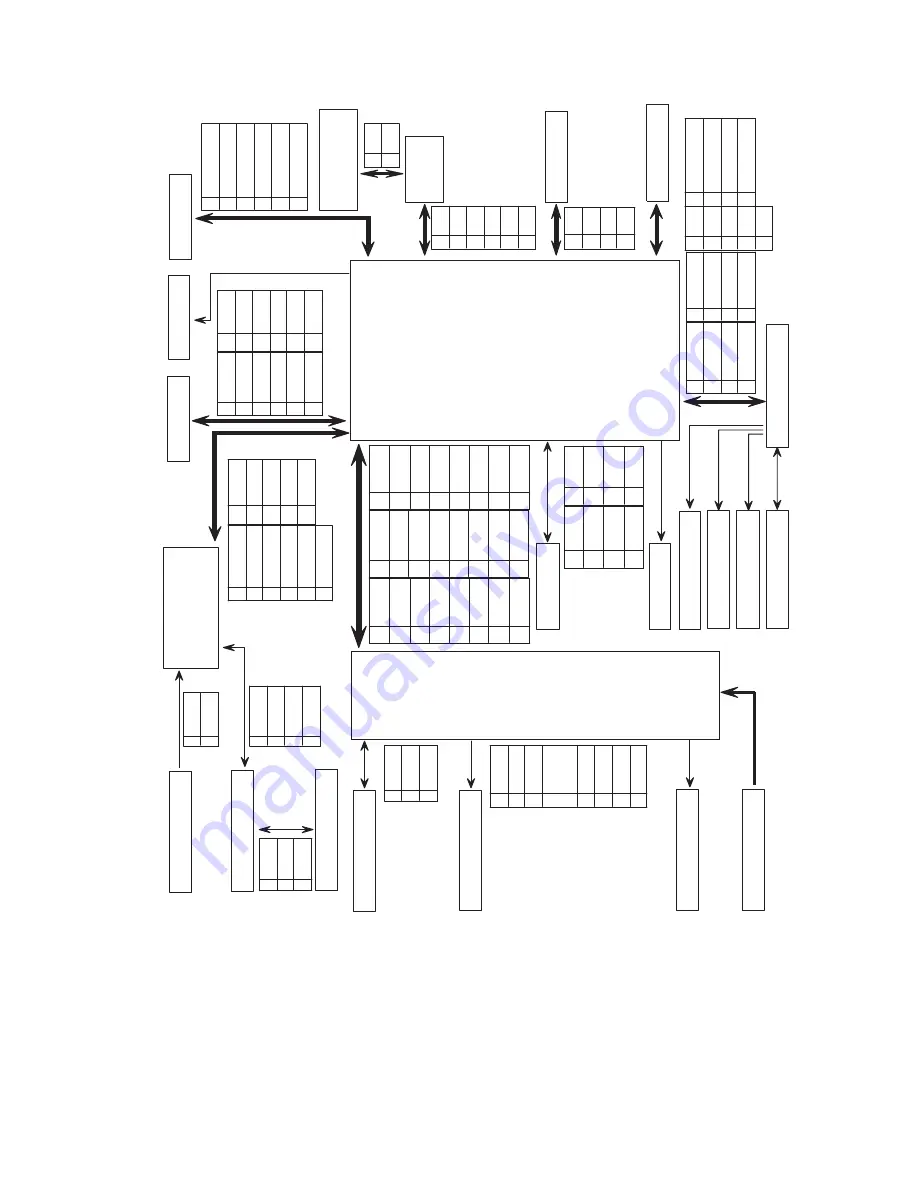
background image

10-5

Connection Diagram

LASER

CO

VE

R

OP

EN

B’

D

PA

NEL

CO

VE

R

JO

IN

T

CO

NNE

CT

OR

B’

D

PT

L

MA

IN

-C

LU

TC

H

EXIT

M

OT

OR

LA

MP

RE

GI

-CLUT

CH

3P

2P

EXI

T

SEN

SO

R

1

VC

C

2

SI

GN

AL

3

GN

D

3P

PRINT CAR

TRIDGE

4P

1

MH

V

2

NC

3

NC

4

OP

C

GN

D

5

NC

6

SU

PP

LY

7

NC

8

DE

V

24

P

SE

NS

OR

B’

D

TH

ER

M

IS

TO

R

2P

1

TH

ER

M

1

2

TH

ER

M

2

1

GN

D

2

P_

REG

I

3

P_

EM

PT

Y

4

VC

C

4P

11

P

1

LS

UC

LK

2

LR

EA

DY

*

3

PM

OT

O

R*

4

GN

D

5

24

V

6

3.

3V

7

VD

O-

8

VD

O+

9

LD

_O

N*

10

GN

D

11

5V

S

12

nH

SY

NC

1

GN

D

2

CA

RT

_CL

K

3

CA

RT

_DA

TA

4

3.

3V

5

P_

EM

PT

Y

6

P_

REG

I

7

TH

ER

M

1

8

TH

ER

M

2

9

P_

SI

ZE

1

10

P_

SI

ZE

2

11

P_

SI

ZE

3

12

P

1

VC

C

2

3.

3V

3

PA

NEL

_T

X

4

PA

NE

L_

RX

5

PA

NE

L_

RE

SE

T

6

GN

D

6P

6P

1

24

V

2

24

V

3

24

VS

4

24

VS

5

GN

D

6

5V

S

2P

1

24

2

24

VS

MA

IN

MO

TO

R

4P

1

PA

_1

2

PA

_2

3

PB

_1

4

PB

_2

8P

1

24

VS

2

24

VS

3

GN

D

4

GN

D

5

GN

D

6

VC

C

7

nS

TA

RT

_S

TO

P

8

M

O

TO

R_

RE

ADY

9

M

O

TO

R_

CL

K

2P

1

24

VS

2

MA

IN

_C

LU

T

3

MP

_C

LU

T

4

RE

GI

_C

LUT

8P

5

MP

_E

M

PT

Y

6

3.

3V

7

PR

O_

M

F

8

GN

D

MP

-CLU

TC

H

RE

GI

SE

NS

OR

3P

1

VC

C

2

SI

GN

AL

3

GN

D

MP

-E

M

PT

Y

3P

2P

2P

3P

1

NC

2

24V

3

DE

V_

PW

M

4

24V

5

M

HV_

PW

M

6

24V

7

GN

D

8

GN

D

9

M

HV_

R

EAD

10

GN

D

11

TH

V_

READ

12

3.3

V

13

TH

V_

EN

14

3.3

V

15

TH

V_

PW

M

16

GN

D

17

24

VS

18

GN

D

19

VC

C

20

VC

C

21

NC

22

P_

EXI

T

23

P_

DU

PL

EX

24

FU

SER

1

3.

3V

2

SC

F_

ST

S

3

SC

F_

CM

D

4

SC

F_

CL

K

5

SC

F_

RDY

6

24

V

7

GN

D

8

GN

D

SC

F

8P

FA

N

3P

-

PRINT CARTRIDGE INTERCONNECT

BOARD

POWER SUPPLY BOARD

AC INPUT

MAIN BOARD

Summary of Contents for Phaser 3425

Page 1: ...Service Manual P h a s e r L a s e r P r i n t e r 3425 ...

Page 2: ......

Page 3: ...nstructions are for use by qualified service personnel only To avoid personal injury do not perform any servicing other than that contained in the operating instructions unless you are qualified to do so PDF Creation December 2005 Last Update February 15 2006 Part Number N A ...

Page 4: ...alk Macintosh Mac OS AppleTalk TrueType2 Apple Chancery Chicago Geneva Monaco and New York are registered trademarks and QuickDraw is a trademark of Apple Computer Incorporated PCL and HP GL are registered trademarks of Hewlett Packard Corporation Windows and Windows NT are registered trademarks of Microsoft Corporation Novell NetWare NDPS NDS and Novell Directory Services are registered trademark...

Page 5: ...on statement indicates an operating or maintenance procedure practice or condition that if not strictly observed could result in damage to or destruction of equipment Warning A warning statement indicates an operating or maintenance procedure practice or condition that if not strictly observed could result in injury or loss of life Product Terms Caution A personal injury hazard exists that may not...

Page 6: ... or in the printer Use caution to avoid personal injury The surface is hot while the printer is running After turning off the power wait 30 minutes Avoid pinching fingers in the printer Use caution to avoid personal injury Use caution or draws attention to a particular component Refer to the manual s for information 0 30 min ...

Page 7: ...rounded outlet If the product loses its ground connection contact with conductive parts may cause an electrical shock Disconnecting Power Turning the power off using the On Off switch does not completely de engergize the printer You must also disconnect the printer power cord from the AC outlet Position the power cord so that it is easily accessible during servicing so that you may power down the ...

Page 8: ...rist strap before applying power to the unit to avoid potential shock After removing a static sensitive assembly from its anti static bag place it on a grounded conductive surface If the anti static bag is conductive you may ground the bag and use it as a conductive surface Do not use freon propelled chemicals as they can generate electrical charges that may damage some devices Do not remove a sta...

Page 9: ...en the supply conductors or between either supply conductor and ground A protective ground connection by way of the grounding conductor in the power cord is essential for safe operation Warning Labels Read and obey all posted warning labels Warning labels are displayed on potentially dangerous printer components As you service the printer check to make certain that all warning labels remain in pla...

Page 10: ...is easily accessible during servicing Warning Do not touch any electrical component unless you are instructed to do so by a service procedure Servicing Mechanical Components When servicing mechanical components within the printer manually rotate drive assemblies rollers and gears Warning Do not try to manually rotate or manually stop the drive assemblies while any printer motor is running Servicin...

Page 11: ...ity compliance and could void the user s authority to operate this product To ensure compliance use shielded interface cables A shielded parallel cable can be purchased directly from Xerox at www xerox com office supplies Xerox has tested this product to internationally accepted electromagnetic emission and immunity standards These standards are designed to mitigate interference caused or received...

Page 12: ...3 Limits Section 2 Limits for harmonic current emissions equipment input current less than or equal to 16A per phase EN61000 3 3 1995 IEC61000 3 3 Part 3 Limits Section 3 Limitation of voltage fluctuations and flicker in low voltage supply systems for equipment with rated current less than or equal to 16A EN55024 1998 CISPR 24 Information technology equipment Immunity characteristics Limits and me...

Page 13: ...or the environment A signed copy of the Declaration of Conformity for this product can be obtained from Xerox Line voltage dips IEC61000 4 11 1994 95 dip for 1 2 cycle 50 Hz 30 dip for 25 cycles 50 Hz Line voltage drop out IEC61000 4 11 1994 95 dropout for 250 cycles 50 Hz CISPR 24 Immunity Phenomena Basic Standard Test Specification ...

Page 14: ...xii Phaser 3425 Laser Printer ...

Page 15: ... Parts 1 8 Consumables 1 9 Supply Life Counter Behavior 1 10 Printer Specifications 1 11 Physical Dimensions and Clearances 1 11 Functional Specifications 1 12 Electrical Specifications 1 12 Environmental Specifications 1 13 Duplex Printing Media Sizes 1 13 Media and Tray Specifications 1 14 2 Theory of Operation Overview of the Phaser 3425 Laser Printer 2 2 Summary of the Printing Process 2 2 Pri...

Page 16: ...u Map 3 9 Error Messages and Codes Summary Table 3 13 Fuser Failure Low Heat or Overheat 0x56 0x57 0x58 3 14 LSU Error or 0x5A 3 15 Jam At Tray 1 2 3 or 0x01 3 16 Jam At Top 0x02 or Jam At Exit 0x03 3 17 Jam At Duplex 0x04 or Jam At Tray 0x05 3 18 Output Tray Is Full or 0x44 3 19 Replace Print Cartridge 0x53 or Invalid Print Cartridge 0x55 3 20 4 General Troubleshooting Introduction 4 2 Preliminar...

Page 17: ...rinter Components 5 2 Front Panel Test Print 5 3 Deletions 5 4 Fusing 5 5 Resolution 5 5 Registration and Skew 5 6 Skips or Smears 5 6 Print Quality Troubleshooting 5 7 6 Adjustments and Calibrations Margin Calibration 6 2 Resetting NVRAM 6 2 6 2 7 Cleaning and Maintenance Service Preventive Maintenance Procedure 7 2 Recommended Tools 7 2 Cleaning 7 2 Printing a Cleaning Sheet 7 3 8 Service Parts ...

Page 18: ...2 No Paper Sensor PL 9 3 44 8 21 Paper Size Sensor PL 9 3 36 8 22 Exit Motor Drive Assembly PL 9 1 20 8 22 Main Fan Assembly PL 9 1 19 8 23 Sub Fan Assembly PL 9 3 35 8 24 Exit Roller Assembly PL 9 3 21 Transport Roller Assembly PL9 3 24 8 25 Laser Assembly PL 9 1 16 8 27 Print Cartridge Interconnect Assembly PL 9 3 53 8 29 Registration Transport Assembly PL 9 1 9 8 30 Registration Sensor PL 9 7 1...

Page 19: ...Drive Motor Assembly 9 16 Exit Drive Motor Assembly 9 17 Registration Transport Assy 9 18 Power Supply Duplex Assembly 9 20 Paper Tray 9 21 Optional Lower Feeder Assembly 9 22 Xerox Supplies 9 25 10 Wiring Diagrams Print Engine Interconnect Diagram 10 2 Map 1 Main Board 10 3 Map 2 Connector Board 10 4 Connection Diagram 10 5 Index ...

Page 20: ...xviii Phaser 3425 Laser Printer ...

Page 21: ...General Information In this chapter Printer Introduction and Overview Printer Configurations Parts of the Printer Phaser 3425 Front Panel Configuration Main Board Service Parts Consumables Printer Specifications ...

Page 22: ...nual is the primary document used for repairing maintaining and troubleshooting the printer To ensure complete understanding of this product participation in Xerox Phaser 3425 Laser Printer Service Training is strongly recommended Phaser 3425 Laser Printer Shown With Optional Tray 3 Insert 3 4 view of Printer with extra tray ...

Page 23: ... ppm letter 24 A4 Resolution 600x600 dpi 1200IQM 600x600 dpi 1200IQM RAM 32 MB expandable to 160MB 32 MB expandable to 160MB Print Language PCL6 PCL6 PostScript 3 Ports USB 2 0 Parallel 10 100 Base TX USB 2 0 Parallel 10 100 Base TX Processor 266 MHz 266 MHz Input paper tray 500 Sheet Optional 2nd 500 Sheet Tray 500 Sheet Optional 2nd 500 Sheet Tray Multi Purpose Tray 100heet 100 Sheet Ouput 250 s...

Page 24: ... the Printer Exterior 1 Tray 1 MPT 6 Output Support 2 Tray 2 500 Sheet Feeder 7 Front Panel 3 Tray 3 Optional 500 Sheet Feeder 8 Top Output Tray Facedown 4 Paper Level Indicator 9 Top Cover 5 Right Main Board Cover 10 Print Cartridge 1 2 5 6 9 10 8 7 3 4 ...

Page 25: ...lect modes of operation for the printer LED indicator Front Panel Button Descriptions Green Ready to Print or Printing Flashing Green Receiving Processing Data Printing or Power Saver Mode 1 LED On Line Status 5 OK select Button 2 Back Button 6 Down Arrow Button Scrolls down menu system 3 Cancel Button 7 Menu Button Cycles through top level menus 4 Up Arrow Button Scrolls up menu system 1 2 3 4 5 ...

Page 26: ...rinter Rear View Rear Panel Configuration Interfaces IEEE 1284 Parallel Ethernet 10BaseT and 100Tx USB Mode Press this selection at Power On Enter Service Diagnostics OK hold the OK button down 1 Power Switch 3 Power Receptacle 2 Rear Panel Interface Ports 4 Rear Jam Access Door 1 2 3 4 ...

Page 27: ... a new Main Board in the printer Note NVRAM parameters are not transferable to the replacement board These include Serial Number and Copy Count Serial number can be reinstalled via CentreWare if the NIC Board is installed or by a downloadable PJL command 1 Memory RAM DIMM 2 Flash Memory ROM DIMM 1 2 RAM DIMM ROM DIMM ...

Page 28: ...1 8 Phaser 3425 Laser Printer Service Manual Service Parts 1 Feed Roller 3 Fuser Assembly 2 Transfer Roller 3 2 1 ...

Page 29: ...General Information 1 9 Consumables 1 Print Cartridge 1 ...

Page 30: ...order to display the near end of life and end of life messages The value currently stored in print cartridge cycles can be viewed using the Read OPC Cycle Service Diagnostic The trigger values are as follows 10K Cartridge 78 000 Toner Low 92 000 Replace Cartridge 5K Cartridge 39 000 Toner Low 46 000 Replace Cartridge Life ratings are based on 5 coverage and an average 4 page job length Consumables...

Page 31: ...ht 13 7 Kg 30 2 Lbs Optional Feeder Cassette Dimensions Value Height 158 mm 6 22 inches Width 380 mm 14 96 inches Depth 446 mm 17 56 inches Weight 5 4 Kg 11 9 Lbs with packaging Clearance Value Top 350 mm 13 78 inches Left 100 mm 3 9 inches Right 100 mm 3 9 inches Front 482 6 mm 19 inches Rear 320 mm 12 6 inches Mounting surface level tolerance Within 2 degrees of horizontal with all four feet in ...

Page 32: ...st print Continuous Operating Printing Speed ppm pages per minute ipm image per minute Letter 25 ppm Simplex 14 ipm Duplex A4 24 ppm Simplex 13 ipm Duplex Cleaning Cycle interval for continuous printing First Print Out in seconds 12 Letter 13 A4 Warm up time Power on Boot 50 seconds or less Characteristic Specification Primary line voltages 100 127 V Printer 90 135 V 13 amp circuit 220 240 V Print...

Page 33: ...10 90 Altitude Operating Low Altitude Setting High Altitude Setting Transportation 0 2 500 meters 8 200 ft 0 2 050 meters 6 726 ft 2 050 2 500 meters 6 726 8 200 ft 0 6 092 meters 20 000 ft Acoustic Noise Idle Printing 35 0db or less 49 0db or less Specification Trays Supported Media Sizes Paper Type Letter Legal US Folio A4 Custom Size Size 215 9 x 279 4 mm 8 5 x 11 in 215 9 x 355 6 mm 8 5 x 14 i...

Page 34: ...er Heavy Plain Paper Transparency Thin Card Stock Thick Card Stock Labels Letterhead Glossy Coated Paper Business Greeting Card CD DVD Labels and Inserts Digital Photo Paper Weight 64 90 g m2 17 24 lb Bond 85 105 g m2 22 28 lb Bond 100 163 g m2 26 60 lb Cover 160 216 g m2 59 80 lb Cover N A 85 105 g m2 22 28 lb Bond 120 163 g m2 81 110 lb N A N A 120 163 g m2 81 110 lb All Trays All Trays All Tray...

Page 35: ...2 Chapter Theory of Operation In this chapter Overview of the Phaser 3425 Laser Printer Print Modes Printer Controls Paper Path of the Printer Duplex Paper Path ...

Page 36: ...r are applied to the supply roller and are then applied to the developer roller in a even layer controlled by the metering blade The developer roller turns against the drum and the toner particles are attracted to the relatively positive latent image The toner forms a visible image on the drum surface 4 Pre Clean The pre transfer lamp exposes the developed suface of the drum lowering the surface p...

Page 37: ...t resolution 300 x 300 dpi to extend print cartridge life 300 Used for printing with a resolution of 300 x 300 dpi 600 Used for printing with a resolution of 600 x 600 dpi Enhanced mode Used for printing on plain paper with an addressable resolution of 1200 x 1200 dpi Exit Sensor Registration Sensor 2 Charging Laser 3 Exposure 7 Fixing 8 Exit 6 Transfer 5 Pre Transfer 4 Development 1 Feeding H R P...

Page 38: ...pecifications on page 1 14 for a complete listing of the media types for each tray Additional media types can be used in Tray 1 MPT After inserting the media in Tray 1 use the front panel controls to select the media type Selective Control Paper Pick When not otherwise controlled by operator selection from the control panel the default paper pick selected at power ON is Tray 2 The tray in the opti...

Page 39: ...k circuits to monitor changes in the printing environment for each section i e charging development transfer fixing etc and adjusting the appropriate supply voltages to achieve optimum printing results Toner Control Print Cartridge installation and Toner Level are detected by the Print Cartridge Interconnect Board and the associated signals are supplied to the Main Board The CRUM not only detects ...

Page 40: ...n in black and the duplex path is shown in grey Duplex Paper Path When duplex print mode is selected the paper is first printed on side one When the image on side one of the paper is fused as detected by the Fuser Exit Sensor the drive motor reverses The paper is fed through the duplexer and back up to the feed roller with side two positioned for printing R1 Print Cartridge Drum R7 Feed Roller S1 ...

Page 41: ...e except as part of a larger component Main Board The Main Board combines the Image Processor and Engine Control functions It contains a 266 MHz Power PC processor and comes with a standard memory capacity of 32 Mbytes The board provides one expansion slot that allows available memory to be expanded up to 160 Mbytes by adding an additional 32 Mbyte 64 Mbyte or 128 Mbyte DIMM H V P S LSU HSYNC Host...

Page 42: ...Q 0 3 4 nIOCS 0 5 6 RCS 0 3 4 nWAIT nWR INT nRD Cent ronic s Connec tor PANEL 5Pin 6 HVPS Inter face 24 16 Power Supply Board 100PIN DIMM L CD Panel 6 0 P i n N et w o r k C o nn e c t o r NIC Card DATA 16 31 nWAIT nRD nWR NPC_RESET IOCS EIRQ Computer Sy s tem c lock 12MHz X t al FS781 Fr equenc y Scaling EMI Attenuator RESET XC61FN 3112M R DA TA 16 31 Video Clock 78 MHz VCLK 32 Memory Data Bus 11...

Page 43: ...Fuser assembly The engine control section provides all of the principle operating voltages and control signals for the following printer operations Main Drive Motor Fuser Assembly High Voltage Power Supply HVPS Laser Scanner Unit LSU Sensors Solenoids Thermistor All parts related to the xerographic process Optional Paper Tray 3 and Tray 1 The HVPS section generates and supplies the following volta...

Page 44: ... image data from the Main Board and uses that information to turn the laser beam on and off as required to correctly expose the drum Image data transfer from the Main Board is controlled by a synchronization signal from the LSU so the vertical scanning line is synchronized with the printed page The LSU contains the following components Laser Diode generates the laser beam Rotating Polygon Mirror s...

Page 45: ...so it adheres to the paper Pressure Roller provides pressure on the opposite side of the print media so the heat roller can embed the melted toner in the media Thermistor monitors the surface temperature of the Heat Roller This information is used to control the heat lamp and thus keep the heat roller at the correct temperature Thermostat prevents overheat damage when unexpected system faults occu...

Page 46: ... red and a Jam error message will display on the control panel Second the signal generated by the sensor tells the Main Board that the paper is almost at the transfer area and it is time to start the xerographic process It is important that the leading edge of the paper enters the transfer area at the same time as the leading edge of the developed image on the drum Paper Transport The registration...

Page 47: ...e Control Panel The signal from the Exit Sensor is also used to control paper feed to the Duplex Unit for duplex print jobs Duplex Unit The Duplex Unit is mounted in the bottom of the printer As paper leaves the fuser and is picked up by the Exit Rollers the drive direction is reversed to send the paper down to the Duplex Unit As the paper passes through the Duplex Unit it activates the Duplex Sen...

Page 48: ...2 14 Phaser 3425 Laser Printer Service Manual ...

Page 49: ...3 Chapter Error Messages and Codes In this chapter Introduction Servicing Instructions Service Diagnostics Error Messages and Codes Summary Table ...

Page 50: ... 3 9 To troubleshoot problems such as start up and power on media paper path print quality or image problems and electrical failures not associated with a front panel message or code refer to the section General Troubleshooting on page 4 1 or to Print Quality Troubleshooting on page 5 1 If an error message or code is not visible on the front panel the Fault History and Jam History list errors repo...

Page 51: ...ccessing Fault History 1 View the printer s fault history on the front panel a Go to Troubleshooting Service Tools Fault History or Jam History Or 2 If the printer is connected to a network and has a TCP IP address view the printer s web page using a web browser a Open a web browser b Enter the printer s IP address as the URL c Select the Troubleshoot link and the fault history will be displayed ...

Page 52: ... Inspect and Clean the Printer 1 Switch OFF printer power 2 Disconnect the AC power cord from the wall outlet 3 Verify the power cord is free from damage or short circuit and is connected properly 4 Remove the Print Cartridge and protect it from light 5 Inspect the printer interior and remove any foreign matter such as paper clips staples pieces of paper dust or loose toner 6 Do not use solvents o...

Page 53: ...o the question is No then follow the instructions for a No reply 5 Troubleshooting Procedures may ask you to take voltage readings or test for continuity at certain test points within the printer For detailed diagrams refer to Chapter 10 Wiring Diagrams on page 10 1 for complete information on test point locations and signal names 6 Troubleshooting Procedures often ask you to replace a printer com...

Page 54: ...a pin that is either RTN Return or SG Signal Ground You can substitute any RTN pin or test point in the printer and you can use FG frame ground in place of any SG pin or test point 5 Before measuring voltages make sure the printer is switched ON the Imaging Unit and the paper trays are in place and the interlock switches are actuated unless a troubleshooting procedure instructs otherwise 6 All vol...

Page 55: ... using the metal frame chassis as the grounding point To locate connectors or test points refer to Wiring Diagrams on page 10 1 for more information Unless otherwise specified the following voltage tolerances are used within this section Stated Measured 3 3 VDC 3 135 to 3 465 VDC 5 0 VDC 4 75 to 5 25 VDC 24 0 VDC 21 6 to 26 4 VDC 0 0 VDC Less than 0 5 VDC ...

Page 56: ...AM access Service diagnostics are to be executed through the front panel by a certified service technician only The printer must be rebooted to enter Service Diagnostics Entering Service Diagnostics 1 Turn the printer power OFF 2 Hold down the OK button and turn the printer back ON 3 Continue to hold the button until the following mesage is displayed on the front panel Diagnostic Mode Press Menu K...

Page 57: ...ghlighted menu Executes the current test item Used to select a data value entered by the user Function Function Function Description Display Tray 3 Interface Selects and checks Tray 3 interface Tray 3 Interface PASS FAIL Test Pattern Pressing OK implements printing the test pattern using either the Simplex or Duplex print routine The displayed location should be checked for normal operation during...

Page 58: ...ns after OK button is pressed and stops when Cancel is pressed Fan Main ON OFF Solenoid Clutch Tray 1 Solenoid When OK button is pressed Tray 1 solenoid is energized for 150 msec then automatically de energized Tray 1 Solenoid ON OFF Tray 2 Solenoid When OK button is pressed Tray 2 solenoid is energized for 150 msec then automatically de energized Tray 2 Solenoid ON OFF Tray3 Solenoid When OK butt...

Page 59: ...per Tray 3 W Out Paper Duplex Sensor Remove Tray 2 pull down on duplex jam gate actuate the sensor and confirm that message changes to Duplex Sensor On Duplex Sensor Off Cover Open Sensor With cover open touch sensor and confirm message changes to Cover Closed Cover Open Reg Sensor With cover open and print cartridge out touch sensor confirm message changes to Reg Sensor With Paper Reg Sensor W Ou...

Page 60: ... with the cover open and the Print Cartridge out PTL ON OFF Laser Scanning Unit LSU Laser Diode Laser Diode turns on when OK is pressed and goes off when Cancel is pressed Laser Diode Test ON OFF Laser Ready Displays the appropriate message when the LSU is ready to print laser diode is on polygon speed stable Laser Ready Test Pass Error Fuser Fuser Control When Target Temp displays default is 150º...

Page 61: ... 0x57 Engine Fuser Over Heat Error 0x58 Laser Errors Laser Failure Polygon motor not ready 0x5A Jam Errors Jam At Tray 1 2 3 Remove All Paper 0x01 Jam At Top Open Top Cover 0x02 Jam At Exit Open Top Cover 0x03 Jam At Duplex Open Top Cover 0x04 Jam At Tray Remove Tray 2 0x05 Memory Errors Insufficient Memory 0x41 Tray Errors Output Tray is Full 0x44 Toner Errors Replace Print Cartridge 0x53 Invalid...

Page 62: ...cycled and the error still appears Troubleshooting Reference Applicable Parts Wiring and Plug Jack Map References Fuser heat lamp Print Engine Interconnect Diagram on page 10 2 Fuser overheat thermostat Thermistor Main Board Troubleshooting Procedure Steps Actions and Questions Yes No 1 Remove Fuser Go to Step 2 2 Check resistance of overheat thermostat Is thermostat open Replace Fuser Go to Step ...

Page 63: ...ppears Troubleshooting Reference Applicable Parts Wiring and Plug Jack Map References LSU Print Engine Interconnect Diagram on page 10 2 Print Engine Controller Board Troubleshooting Procedure Steps Actions and Questions Yes No 1 Check that the laser connectors are properly seated Go to Step 2 Reseat the connectors 2 Use the embedded diagnostics to check laser motor operation Does the laser motor ...

Page 64: ...operation of the tray solenoids Do the tray solenoids operate correctly Go to Step 2 Replace the inoperative solenoid 2 Using the embedded diagnostics check operation of the Regi Clutch and Feed Clutch Do the clutches operate correctly Go to Step 3 Replace the defective clutch 3 If paper feeds into the printer and the Jam error message appears use the embedded diagnostics to check feed sensor oper...

Page 65: ...rocedure Steps Actions and Questions Yes No 1 Does paper jam in front of or just inside the Fuser Replace the Power Supply Board Go to Step 2 2 If paper jams in the fuser and the fuser discharge roller after leaving the Regi Sensor use the embedded diagnostics to check operation of the Regi Sensor Does the sensor operate correctly Replace the Main Board Replace the damaged sensor 3 Does the error ...

Page 66: ...rconnect Diagram on page 10 2 Duplex Assembly Power Supply Board Main Board Transport Roller Shaft Assembly Troubleshooting Procedure Steps Actions and Questions Yes No 1 Does paper jam after reversal but before reaching duplex sensor Replace Transport Roller Shaft Assembly Go to Step 2 2 Does problem recur Replace Duplex Assembly Complete 3 If paper jam occurs at the Feed Roller use the embedded ...

Page 67: ...arts Wiring and Plug Jack Map References Tray Full Sensor Print Engine Interconnect Diagram on page 10 2 Main Board Troubleshooting Procedure Steps Actions and Questions Yes No 1 Check the operation of the sensor actuator Does the actuator bind or show signs of damage Replace sensor actuator Go to Step 2 2 Use the embedded diagnostics to check operation of the Tray Full Sensor Does the sensor oper...

Page 68: ...ack Map References Cover open interlock switch Print Engine Interconnect Diagram on page 10 2 Switch actuator lever Main Board Troubleshooting Procedure Steps Actions and Questions Yes No 1 Is the switch actuating lever on top of the Print Cartridge damaged Replace Print Cartridge Go to Step 2 2 Is the Cover Open Switch connector CN20 properly connected to the Main Board Go to Step 3 Reconnect CN2...

Page 69: ...4 Chapter General Troubleshooting In this chapter Introduction Preliminary Procedures Front Panel Troubleshooting Paper Size Switch Assembly Power Supply Troubleshooting Media Jams and the Paper Path ...

Page 70: ...he printer 4 Is the other end of the AC power cord plugged into a grounded three pronged AC wall outlet 5 Is the printer located in an area where the temperature and humidity are moderate and stable as recommended in the General Information section 6 Is the printer located in an area that is free of dust 7 Is the printer located away from water outlets steamers electric heaters volatile gases or o...

Page 71: ... reseat all connections to the Main Board 2 Remove and reseat the Front Panel connector 3 Replace the Front Panel wiring harness 4 Replace the Front Panel 5 Replace the Main Board Front Panel Continually Displays Close Cover or Check Cartridge 1 Verify that the Top Cover is securely closed 2 Ensure that the Print Cartridge is properly installed and securely seated 3 Verify that the Top Cover Print...

Page 72: ...ull Sensor 5 Replace the Output Full Sensor Harness 6 Replace the Exit Roller Assembly 7 Replace the Main Board Paper Size Switch Assembly Paper size and tray installation is determined by a combination of ON OFF statuses of the upper middle and lower switches of the Switch Paper Size Assembly Paper size Switches Upper Middle Lower LEGAL14 ON ON OFF LEGAL13 ON OFF ON EXECUTIVE OFF ON ON B5 OFF OFF...

Page 73: ...AC wall outlet Is there approximately 110 VAC or 220 VAC if the printer is a 220 V model at the AC wall outlet Go to Step 2 Notify the customer of improper AC output from the outlet 2 a Check the power cord for defects or a loose connection Replace or reseat the power cord Go to Step 3 3 a Disconnect the Power Cord and turn the AC switch ON b Check the AC Switch Harness for continuity Replace the ...

Page 74: ...per in the tray 7 Prior to performing any of the Jam procedures verify that the Registration and Fuser Exit actuators are not being held in the actuated position and that they move freely without binding Paper Mis feed from Tray 1 MPT Troubleshooting References Procedure Applicable Parts Wiring and Plug Jack Map References Tray 1 Actuator Tray 1 Assembly Step Action and Questions Yes No 1 a Is pap...

Page 75: ...tly 2 a Is the tray damaged b Are parts missing Replace Tray 2 Assembly Go to Step 3 3 a Is Tray 2 Feed Solenoid release arm binding or unable to move freely Refer to Service Diagnostics Menu Map on page 3 9 Repair or replace solenoid Go to Step 4 4 a Does Tray 2 Pick Roller rotate when the Solenoid actuates Refer to Service Diagnostics Menu Map on page 3 9 Go to Step 5 Replace Pick Roller Assembl...

Page 76: ...a Is the tray damaged b Are parts missing Replace Tray 3 Assembly Go to Step 3 3 a Is Tray 2 chute obstructed Clear obstruction Go to Step 4 4 a Is the interface connector between the printer and Tray 3 damaged Replace interface harness Go to Step 5 5 a Does Tray 3 Pick Roller rotate when the Solenoid actuates Refer to Service Diagnostics Menu Map on page 3 9 Go to Step 5 Replace Tray 3 Assembly 6...

Page 77: ...rd Step Action and Questions Yes No 1 Is the Registration Feed Sensor Actuator damaged or binding Repair or replace the actuator and or sensor Go to Step 2 2 Do the Registration Rollers turn freely Go to Step 3 Replace Registration Assembly 3 Does the Transfer Roller turn freely Go to Step 4 Replace the Transfer Roller 4 Inspect the paper transport area for obstructions Clear obstruction Go to Ste...

Page 78: ...damaged or binding Repair or replace the actuator and or sensor Go to Step 2 2 Is the Registration Sensor Actuator damaged or binding Repair or replace the actuator and or sensor Go to Step 3 3 Is paper wrapped around the Fuser rollers or blocking Fuser exit Remove paper and clean Fuser rollers Go to Step 4 4 Is Fuser operational the Fuser Rollers turn freely when the motor is on Go to Step 5 Repl...

Page 79: ...ged or binding Repair or replace the actuator and or sensor Go to Step 2 2 Inspect the Exit Roller Assembly Is it damaged or binding Replace the Exit Roller Assembly Go to Step 3 3 Inspect the Fuser Is any paper wrapped around the Fuser rollers Remove obstruction and clean Fuser rollers Go to Step 4 4 Is the Fuser Assembly operational rotates when the Fuser motor is on Go to Step 5 Replace the Fus...

Page 80: ... Sensor Actuator damaged or binding Repair or replace the actuator and or sensor Go to Step 2 2 Inspect the Exit Roller Assembly Is it damaged or binding Replace the Exit Roller Assembly Go to Step 3 3 Inspect the Duplexer Is any paper wrapped around the Duplex Rollers Remove obstruction and clean rollers Go to Step 4 4 Is the Transport Roller Assembly operational rotates freely without binding Go...

Page 81: ...Sensor Actuator damaged or binding Repair or replace the actuator and or sensor Go to Step 2 2 Use the embedded diagnostics to check the Duplex Sensor Is the sensor operational Go to Step 3 ReplaceDuplex Sensor 3 Inspect the Duplex Assembly Is any paper wrapped around the Duplex rollers Remove obstruction and clean rollers Go to Step 4 4 Is the Duplex Roller operational rotates freely without bind...

Page 82: ...properly seated Does the error clear after reseating the cartridge Complete Go to Step 2 2 Reseat all harness connections to the Print Cartridge Interconnect Board Does the error clear Complete Go to Step 3 3 Check continuity between the Print Cartridge Interconnect Board and CN6 on the Main Board Does the harness show continuity Go to Step 4 Replace Harness 4 Check Print Cartridge Does the cartri...

Page 83: ...5 Chapter Print Quality Troubleshooting In this chapter Print Quality Problems Overview Defects Associated with Specific Printer Components Front Panel Test Print Print Quality Troubleshooting ...

Page 84: ... defect is still present when printing on approved media from an unopened ream of paper then components software applications and environmental conditions need to be researched When analyzing a print quality defect first determine if the defect is repeating or random Repeating defects can often be associated with a particular component The visible surfaces of all rollers should be inspected for ob...

Page 85: ...ed paper from a fresh unopened ream whenever possible to check the image quality of prints Make five copies of the test print Discard the first two prints and retain the remaining prints for image quality analysis Assembly Component Distance between Defects Typical Defect Print Cartridge Developer Roller 49 mm 1 93 in Horizontal image band Drum 95 mm 3 74 in White spots on black image or black spo...

Page 86: ...5 4 Phaser 3425 Laser Printer Service Manual Deletions Inspect the test print for the presence of deletions or unprinted spots If these are found go to Spot or Vertical Deletions on page 5 9 ...

Page 87: ...e 5 10 Resolution Observe the three resolution check points on several test prints Ensure that the 2 pixel horizontal vertical and diagonal lines are clear and continuous The diagonal lines might appear to be narrower than the others Characters in the text paragraphs should be uniform and equal in density The halftone patches should be uniform in appearance If the image does not meet the criteria ...

Page 88: ...uld be aligned perpendicular to the target crosshairs and should be within 2 0 mm of the target crosshairs each line on the target is 1 0 mm If the image does not meet the criteria refer to Skewed Image on page 5 10 Skips or Smears Check the test print in the indicated areas for loss stretching or distortion of the image in bands across the process direction that make the image seem distorted blur...

Page 89: ...e was not removed from the cartridge Low toner Transfer Roller Laser contamination or obstruction Incorrect high voltage output Low ambient temperature 10º C Verify paper meets printer specifications Print 20 to 30 pages using the recommended paper Verify that the Remote Control Panel is not set to Economode or that Toner Density menu is not set to light Ensure that the sealing tape has been remov...

Page 90: ... the previous page prints on consecutive pages Operating environment Media paper Print Cartridge Transfer Roller Fuser assembly Incorrect high voltage outputs Printer is installed in specified environment Verify that paper meets printer specifications Print 20 to 30 pages using recommended paper Determine ghosting pitch and replace the corresponding assembly NOTE Refer to Defects Associated with S...

Page 91: ...lace Print Cartridge NOTE Refer to Defects Associated with Specific Printer Components on page 5 2 for defect pitch Remove the Transfer Roller and clean dust off If deletions repeat every 57 mm replace Transfer Roller Horizontal Bands Dark bands appearing in the horizontal direction Print Cartridge Fuser Assembly Transfer Roller Incorrect high voltage outputs Laser Assembly Replace the Print Cartr...

Page 92: ...ansportation areas for proper operation Inspect clean replace Fuser assembly as necessary Skips Smears Skips loss or stretching of the image in bands across the process direction Smears the distortion of the image in bands across the process direction Causes image to appear blurred or compressed Paper transportation Main drive motor assembly Fuser Assembly Print Cartridge Inspect paper transportat...

Page 93: ...6 Chapter Adjustments and Calibrations In this chapter Margin Calibration Resetting NVRAM ...

Page 94: ...L5e The default setting for Simplex Top Left is 0 0 Margins Duplex Top Left The Duplex Top and Left adjustment provides a method of changing the margin settings for the first imaged side of a duplex page The duplex margin settings can be used with or without a print driver The default setting for Duplex Top Left is 0 20 Resetting NVRAM Resetting NVRAM returns all the System Control Board NVRAM sto...

Page 95: ...7 Chapter Cleaning and Maintenance In this chapter Service Preventive Maintenance Procedure Recommended Tools Cleaning Printing a Cleaning Sheet ...

Page 96: ...inted Recommended Tools Toner vacuum cleaner Clean water Clean dry lint free cloth Black light protective bag Cleaning Caution Never apply alcohol to any parts in the printer Never use a damp cloth to clean up toner If you remove the Print Cartridge place it in a light protective bag Exposure to light can degrade its performance and result in early failure 1 Record number of sheets printed 2 Print...

Page 97: ... at the Ready state and with approved paper loaded in the tray 2 Press the Menu button on the Front Panel Menu Information displays 3 Use the arrow buttons to scroll through the menu until Troubleshooting displays on the bottom line 4 Press OK Troubleshooting Margins displays 5 Press the down arrow button to display Service Tools on the bottom line and press OK Service Tools Test Prints displays 6...

Page 98: ...7 4 Phaser 3425 Laser Printer Service Manual ...

Page 99: ...8 Chapter Service Parts Disassembly In this chapter Overview General Notes on Disassembly Removing Service Parts and Consumables Print Engine Disassembly ...

Page 100: ...l a part simply reverse the Removal Procedure shown In some instances the Replacement Procedure is included because it may contain special steps For specific assemblies and parts refer to the Parts Lists on page 9 1 Standard Orientation of the Printer When needed the orientation of the printer is called out in the procedure for locating printer parts Refer to the printer orientation graphic for lo...

Page 101: ...y match the names that appear in the Parts List For example a part called the Registration Transport Assembly may appear on the Parts List as Assembly Transport Regi Caution Many parts are secured by plastic tabs DO NOT over flex or force these parts Do not over torque the screws threaded into plastic parts Always use the correct type and size screw Using the wrong screw can damage tapped holes Do...

Page 102: ... printer 3 Grasp the handle on the top of the Print Cartridge and pull it toward the front of the printer while also lifting it out of the printer 4 Place the Print Cartridge in a light proof bag or other light proof container Caution Leaving the Print Cartridge exposed to light for periods in excess of a few minutes can degrade its performance and result in early failure Transfer Roller Removal P...

Page 103: ...d contact goes on the gear side of the Transfer Roller 5 Slide the roller slightly to the right so the end of the shaft clears the lip on the printer case and lift the Transfer Roller together with the Bearing Clips and the Transfer Roller Gear out of the printer Fuser Removal PL 9 3 40 Warning The Fuser may be hot Turn off power and allow at least 5 minutes for the Fuser to cool before removal 1 ...

Page 104: ...t screws go on the bottom Reassembly Caution When reinstalling the Fuser insert it gently and be careful not to force the gears Make sure that the Fuser is firmly seated on both ends and that the ground wire lower LEFT end is not trapped under Fuser The long screws go on top and the short screws go on the bottom Failure to reconnect the ground wire can result in a premature printer failure If the ...

Page 105: ... and remove the power cord from the wall outlet 2 Remove the 2 screws securing the Right Cover 1 to the back of the printer 3 Slide the cover toward the back of the printer to disengage the 3 retaining hooks on the lower edge of the cover then lean the top of the cover outward and remove it from the printer 1 ...

Page 106: ...he upper screw Note The rear cover will have to be closed most of the way when sliding the left hand cover assembly to the rear so the cover will clear the bottom lip of the rear cover The rear cover will then have to be opened slightly to clear the retaining boss for the upper screw 3 Slide the cover toward the back of the printer to disengage the 3 retaining hooks on the lower edge of the cover ...

Page 107: ...rom the printer 3 Open Tray 1 the rear cover and the front section of the Top Cover Note If the NIC Card is installed remove it page 8 17 to access the connectors on the Main Board 4 Disconnect CN 4 Front Panel from the Main Board and CN 2 Cover Open from the Cover Interconnect Board 5 Remove 3 screws 2 at the top front and 1 on the rear edge that secure the Top Cover to the printer assembly CN 4 ...

Page 108: ...the Top Cover Assembly from the printer Caution Remove the cover carefully while feeding the cables and connectors removed from the Main Board through the chassis access holes Tray 1 Cover Assembly PL 9 1 2 1 Power down the printer and remove the power cord from the wall outlet 2 Open Tray 1 Caution Use caution when pushing outward on the top of the slot tracks in the next Step If you exert too mu...

Page 109: ...he Tray Link from the left cover slot Next flex the top of the right track and release right Tray Link 4 Raise the cover slightly so the boss located behind the hinge on the left side of the cover clears the hinge pin mount and slide the cover to the right and pull out to remove it from the printer 1 Tray Link 2 Link Pin 3 Slot Track 1 Tray 1 Cover 2 Hinge 1 2 3 1 2 ...

Page 110: ...unted under the pressure arm of the Retard Assembly Be careful not to lose the spring When reinstalling the Retard Assembly ensure that the spring is securely mounted and seats correctly over the boss on the chassis When properly installed the Retard pressure arm should move smoothly up and down against the spring pressure 4 Pull outward to remove the Retard Feeder Assembly with the Tray 1 Empty S...

Page 111: ...d remove the Links 6 Remove the two screws securing the Front Cover to the printer unlatch the two retaining hooks on each side and remove the Front Cover Tray 1 Lift Plate PL 9 1 3 1 Remove the Front Inner Cover page 8 12 2 Disconnect the 2 Bias Springs from the metal frame Note In some cases the Bias Springs will slip off of the plastic mounting arms on the Lift Plate easily and they can be disc...

Page 112: ...PL 9 2 3 1 Open the rear cover and remove the screw that secures the strap to the rear of the printer Note You can also pry the cover end of the strap off the retainer and slide it free of the cover while leaving it and the screw attached to the rear of the printer 1 ...

Page 113: ...ide the rear cover to the left to free the right hinge pin see above and remove the rear cover 4 If you are replacing the rear cover assembly remove the strap for use on the new cover assembly Pry the top end of the strap off of the retaining boss on the rear cover Slide the strap down to remove it from the rear cover Front Panel Assembly PL 9 2 1 8 1 Remove the Print Cartridge page 8 4 and protec...

Page 114: ...cess the interlock switch however the Right Cover must be removed in order to disconnect the interlock switch connector CN 2 from the Cover Interconnect Board Routing the switch cable to the Main Board is easier with the Top Cover removed 1 Remove the Print Cartridge page 8 4 and protect it from light 2 Remove the Top Cover Assembly page 8 9 3 Open the front section of the Top Cover to access the ...

Page 115: ...he Right Cover Assembly page 8 7 Caution Observe proper ESD procedures when removing or replacing any circuit boards in the printer Refer to General Notes on Disassembly on page 8 3 2 Remove 2 thumbscrews securing the NIC Board to the rear edge of the Main Board mounting bracket 3 Pull up on the front edge of the NIC Board to remove it from the connector CN 9 on the Main Board and remove the NIC B...

Page 116: ...s in the printer Refer to General Notes on Disassembly on page 8 3 2 Disconnect all connectors from the Main Board 3 Remove 6 screws securing the Main Board to the Main Board Bracket 4 on the right side of the printer and 2 from the rear of the printer Cover Open CN20 Erase Lamp CN17 Power Supply Board CN18 Main Motor CN11 CN12 CN16 Connector Board CN14 Laser CN10 Exit Motor CN8 Sub Fan CN21 Print...

Page 117: ...are if the NIC Board is installed or via a downloadable PJL command Replacement Notes Note When reinstalling the Main Board the short machine screw goes in the top right corner of the board Main Drive Assembly PL 9 1 11 1 Remove the Right Cover Assembly page 8 7 2 Disconnect CN 14 connecting the Registration Clutch to the Connector Board see Map 2 Connector Board on page 10 4 3 Disconnect CN 1 fro...

Page 118: ...he Registration Clutch to the Feed Roller Shaft and remove the Registration Clutch 6 Remove the screw securing the Cover Interconnect Board to the Main Drive and move it out of the way 7 Remove 6 screws that secure the Main Drive to the printer chassis and remove the Main Drive 1 1 ...

Page 119: ...ositioned Tray 2 Solenoid PL 9 1 28 1 Remove the Main Drive Assembly page 8 19 2 Disconnect CN 10 between the Tray 2 Solenoid and the Connector Board 3 Remove 2 screws that secure the Tray 2 Solenoid to the chassis and remove the Tray 2 Solenoid Tray 2 No Paper Sensor PL 9 3 44 1 Remove the left cover from the printer page 8 8 2 Disconnect CN 2 to Registration Sensor from the sensor board 3 Discon...

Page 120: ...removing the rear crossbar However to provide improved access remove the crossbar screw above the Paper Size Sensor and loosen the screw on the other side so you can swing the crossbar out of the way 5 On the left side of the printer remove 2 screws one on either side of the rear crossbar that secure the Paper Size Sensor to the printer chassis 6 Pull up on the sensor assembly until it is clear of...

Page 121: ...tween the screw head and the motor Main Fan Assembly PL 9 1 19 1 Remove the Top Cover Assembly page 8 9 2 Disconnect the Main Fan connector CN 15 from the Main Board see Map 1 Main Board on page 10 3 Note If you wish you can loosen the screws securing the Laser Assembly and tilt it to provide additional access to remove the cable This will be necessary when routing the cable back under the Laser A...

Page 122: ...rews securing the Laser Assembly sufficiently to route the fan cable under the laser Sub Fan Assembly PL 9 3 35 1 Remove the Top Cover Assembly page 8 9 2 Disconnect the Sub Fan connector CN 21 from the Main Board Note If you wish you can loosen the screws securing the Laser Assembly and tilt it to provide additional access to remove the cable This will be necessary when routing the cable back und...

Page 123: ...te If not already done during removal loosen the screws securing the Laser Assembly sufficiently to route the fan cable under the laser Install the Sub Fan with the label facing in to ensure proper air flow Exit Roller Assembly PL 9 3 21 Transport Roller Assembly PL9 3 24 1 Remove the Print Cartridge page 8 4 and protect it from light 2 Remove the Top Cover Assembly page 8 9 1 Stopper 2 Sub Fan 1 ...

Page 124: ...xit Roller gear to the shaft Remove the gear 5 Repeat the procedure for the bearing on the right end of the Exit Roller shaft and remove the shaft 6 Lift the Exit Shaft Assembly out of the exit frame Caution The Exit Idler Roller Assemblies are not captured in the exit frame and can be dropped 7 Lift the Exit Idler Roller Assemblies out of the exit frame 1 Bearing 2 Exit Roller 3 Exit Idler Roller...

Page 125: ...port Roller Shaft Assembly gear to the shaft and remove the gear 11 Repeat the procedure for the bearing on the right end of the Transport Roller Shaft Assembly and remove the shaft 12 Slide the bearings off both ends of the Transport Roller Shaft Assembly Note The bearings can be left in place on the shaft unless they or the shaft are being replaced Note On reassembly ensure that the Output Full ...

Page 126: ...ve 3 screws securing the Laser Assembly to the printer chassis and lift the Laser sufficiently to access the harness Caution Be careful not to touch the window on the underside of the Laser Assembly 6 Carefully peel back the foam pad securing the laser harness to the bottom of the Laser Assembly and disconnect the 2 harness connectors from the Laser Note If the foam pad is damaged during removal i...

Page 127: ...aser Assembly page 8 27 2 If the NIC Board is installed remove it page 8 17 3 Disconnect CN 4 CN 7 CN 8 and CN 9 from the Print Cartridge Interconnect Assembly 4 Disconnect CN 6 from the Main Board 5 Remove the 3 screws securing the Print Cartridge Interconnect Assembly and remove the Assembly ...

Page 128: ...tion Sensor 4 Remove the 4 screws that secure the Registration Transport Assembly to the chassis 5 Lift up on the latch handle at the front and remove the gear cap item 1 at the right end of the Registration Transport Assembly Note The gear cap is the same color black as the printer frame and can be difficult to see Look at the right end of the Registration Transport Assembly and you will see the ...

Page 129: ...egistration Transport Assembly page 8 30 2 Remove 1 screw accessed from the bottom of the Assembly that secures the Registration Sensor to the Registration Transport Assembly and remove the Sensor Holder and the Sensor Tray 1 Feed Roller Assembly PL 9 3 2 1 Remove the Front Inner Cover Assembly page 8 12 1 Regi Sensor 2 Sensor Holder 1 2 ...

Page 130: ...e Tray 1 Solenoid to the Connector Board see Map 2 Connector Board on page 10 4 3 Remove 2 screws securing the Tray 1 Solenoid item 1 to the chassis and remove the solenoid Note The ground wire will also be removed at this time Be sure to replace it when replacing the solenoid 1 ...

Page 131: ... the rack with the 2 bushings that secure the rack to the Tray 1 Feed Roller Shaft 5 Remove 1 screw on the right side of the printer that secures the bracket over the right end of the Feed Roller Shaft Remove the bracket and the Tray 1 Gear 1 Bushing 2 Tray 1 Pick Up Rack 1 Bracket 2 Tray 1 Gear 2 1 2 1 ...

Page 132: ...aining hole in the chassis then rotate the bearings to the rear to remove them from the shaft 7 Slide the shaft towards the right side far enough to free the left end of the shaft as shown by below 8 Pull the left end of the shaft forward while sliding the right end of the shaft free as shown by below Remove the Pick Up Assembly from the printer 1 2 ...

Page 133: ...ecessary to rotate the Pick Roller for removal release the solenoid then rotate the shaft gear clockwise 3 Release the securing tab on the Pick Roller slide it to the right and then using a small flat screwdriver gently pry the Pick Roller free of the shaft as shown by below Note After installation ensure that the Pick Roller does not rotate independently of the shaft If it does it is not properly...

Page 134: ...Assembly PL 9 3 7 1 Remove the Front Inner Cover page 8 12 2 Remove 2 screws and drop the Retard Roller Frame Assembly Tray 2 Paper Pick Assembly PL 9 3 67 1 Remove the Front Inner Cover Assembly page 8 12 2 Remove the Main Drive Assembly page 8 19 Roller Ass y ...

Page 135: ...Service Parts Disassembly 8 37 3 On the right side of the printer press down the retaining tab and remove the Feed Roller Shaft Gear Assembly from the Feed Roller Shaft ...

Page 136: ...ual 4 Turn the printer upside down remove 4 screws and remove the 2 Bottom Cross Bars from the printer Caution The Tray Full actuator is exposed with the top cover removed Be careful when you turn the printer over to avoid damaging the actuator ...

Page 137: ...up assembly to the front corners of the Duplex Guide Plate 6 Using a screwdriver pry up the locking tab and remove the stopper on the left side of the printer 7 Remove the screw securing the ground wire on the right side of the Duplex Guide Plate 8 Remove the Duplex Guide Plate from the printer 1 ...

Page 138: ... printer Pull out to free the bearing from the chassis then rotate the bearing to the rear and remove it from the shaft 10 Remove 4 screws securing the Paper Pick Assembly slide the assembly to the right side of the printer lift the left end and slide the assembly up and out to the left side of the printer 1 Feed Roller 2 Pick Up Roller 2 1 1 ...

Page 139: ...embly page 8 36 2 Remove the spring release from the shaft on the left side of the pick roller shaft Caution Be careful not to drop the spring during removal 3 Remove the bearing on the right end of the pick roller shaft and slide the end of the shaft to the right to disengage the shaft coupling 4 Pull the center shaft out of the retaining clips 5 Pull the segmented roller off of the roller core 6...

Page 140: ...r be careful not to damage the springs Power Supply Board PL 9 1 13 1 Remove the Duplex Guide Plate from the printer page 8 36 Steps 1 through 8 2 Slide the Tray 2 Paper Out Actuator item 1 to the left until the end is free of the retainer clip then lift up to remove it from the printer 1 1 2 Left Right ...

Page 141: ...Duplex Assembly from its mounting location Note The screw that secures the ground wire to the back edge of the assembly is the short machine screw Caution Do not attempt to remove the Power Supply Board Assembly from the printer until you first disconnect all 5 connectors ...

Page 142: ...CN 1 CN 2 CN 3 CN 4 and CN 101 from the Power Supply Board then remove the Power Supply Board Assembly to a work surface with the Power Supply up Reassembly Notes Note CN3 must be dressed correctly for reassembly If CN3 is pulled too far forward assembly will be difficult 1 ...

Page 143: ...emove 4 screws securing the Power Supply Board to the Duplex Assembly and remove the board Exit Sensor PL 9 3 62 1 Remove the Power Supply Board page 8 42 2 Remove 2 screws securing the Exit Sensor to the chassis and remove the Exit Sensor 1 Power Supply Board 2 RH Guide Duplex 3 LH Guide Duplex 1 3 2 ...

Page 144: ...8 46 Phaser 3425 Laser Printer Service Manual ...

Page 145: ...9 Chapter Parts Lists In this chapter Using the Parts List Print Engine Parts Xerox Supplies ...

Page 146: ...de up of the individual parts called out in parentheses 7 The notation with X Y following a part name indicates an assembly that is made up of components X through Y For example 1 with 2 4 means part 1 consists of part 2 part 3 and part 4 8 An asterisk following a part name indicates the page contains a note about this part 9 The notation NS next to a part indicates that pariticular part is not sp...

Page 147: ... Parts Main Unit 7 16 11 32 38 30 13 18 8 6 0 3 2 1 2 2 2 4 5 3 1 3 2 3 3 3 4 3 4 3 5 3 6 1 14 14 2 14 1 14 3 17 17 33 9 22 34 22 29 28 19 20 12 31 27 36 35 27 1 27 2 27 3 38 38 42 24 24 1 24 2 24 4 24 3 25 25 1 25 2 25 3 23 21 26 37 10 41 41 1 41 2 39 40 15 ...

Page 148: ...Exit Motor Assembly 1 127K44870 13 Power Supply Board 110 Volts Power Supply Board 220 Volts 1 1 105K27081 105K27091 14 Duplex Guide Plate with 14 1 14 3 1 NS 15 Bracket Dummy Control NS 16 Laser Assembly 1 122K02450 17 Cross Bar 2 NS 18 T ray 2 Empty Actuator 1 120E26090 19 Fan DC Main 1 127E14630 20 Stopper Fan NS 21 Gear Transfer Rol l 1 007N01013 22 Gear Regi Z25 NS 23 T ransfer Roller 1 022E2...

Page 149: ...19270 33 PMO Cap TR NS 34 PBA Sub Cover Joint NS 35 Bracket P Shaft MP NS 36 Bearing Pick Up NS 37 Gear Pick Up Cam NS 38 E Ring NS 39 CBF Harness SMPS NS 40 CBF Harness MPF Joint NS 41 Network Interface N A 42 Fan DC Sub 1 127N07300 Service Parts List 9 1 Main Unit Continued No Name Description Qty Part Number ...

Page 150: ...Parts Lists 9 7 Covers 1 1 3 2 1 3 3 1 3 3 1 3 7 1 3 1 1 3 4 1 3 5 1 3 6 1 3 8 1 2 1 3 1 3 9 1 3 10 1 3 10 1 2 1 1 2 2 5 3 2 3 1 3 5 3 2 3 8 3 3 3 7 3 6 3 4 0 4 2 1 2 2 6 1 1 1 1 1 3 1 1 4 1 1 2 1 1 ...

Page 151: ...1 1 3 NS 1 1 Front Panel with 1 1 1 1 1 4 003N00979 1 2 Top Cvr Intlck Switch with 1 2 1 and 1 2 2 002N02471 1 3 Top Cover with 1 3 1 1 3 10 1 002N02470 2 Right Cover Assembly with 2 1 and 2 2 1 802K69580 3 Rear Cover Assembly with 3 1 3 8 1 802K69591 4 Left Cover 1 802E66540 5 Front Inner Cover 1 802E66550 6 Output Tray Cover 1 802E66560 ...

Page 152: ...ssembly 1 2 6 6 2 1 7 2 2 2 2 2 3 2 4 2 4 1 2 4 2 2 4 3 7 1 7 2 7 3 7 8 7 4 7 5 7 6 7 7 5 14 15 16 16 15 8 9 10 19 19 1 19 2 19 3 19 4 19 20 34 37 33 21 22 23 20 20 24 20 22 35 28 4 3 26 27 29 30 17 0 31 32 66 36 36 1 36 3 36 2 ...

Page 153: ...7 1 7 8 1 019N00853 8 Guide P Transfer NS 9 PMO Holder Plate Saw NS 10 IPR Plate Saw NS 11 12 13 14 Guide P Regi Upper NS 15 Spring ETC Lever NS 16 Holder M Bushing TX NS 17 Guide Plate Paper NS 18 19 Exit Idler roller Assy with 19 1 19 4 1 059K39110 20 Bearing 4 013E25770 21 Exit Shaft Roller Assy 1 006K29340 22 Exit Gear 2 013E25780 23 Holder M Bushing Exit NS 24 Transport Exit Shaft Assy 1 006N...

Page 154: ...able Tie NS 33 Actuator Out Full NS 34 Photo Interrupter NS 35 Connector NS 36 Paper Size Sensor Assy with 36 1 36 3 1 110K14290 37 Harness Out Full NS Service Parts List 9 3 Frame 1 Assembly Continued No Name Description Qty Part Number ...

Page 155: ...67 2 67 3 67 3 67 4 67 5 67 5 67 13 67 7 67 9 67 6 67 7 67 8 67 12 67 9 67 10 67 13 39 67 1 1 68 1 68 13 68 S 68 5 70 39 42 65 45 46 47 48 49 60 50 51 57 56 58 56 59 41 60 63 63 38 50 38 44 38 43 52 66 61 62 71 0 64 68 3 68 2 68 10 68 4 68 6 68 12 68 11 68 9 68 8 68 7 DIME Screw 40 ...

Page 156: ...ler NS 48 ELA HOU Varistor NS 49 IPR P GND Motor Main2 NS 50 IPR P GND Guide TR NS 51 AC Harness Assy 1 962K26720 52 Hinge M Front Guide Dup NS 53 Print Cartridge Interconnect Board 1 001N00468 54 55 56 Spring ETC Guide DEVE NS 57 PMO Guide DEVE L NS 58 PMO Guide DEVE R NS 59 Terminal P TR Cardinal NS 60 Sheet Cover TR NS 61 IPR P Ground Plate Paper NS 62 Exit Sensor 1 130E11100 63 Terminal P HV C...

Page 157: ...r Service Manual 68 Tray 2 3 Retard Assy with 68 1 68 13 1 022E29540 69 Shaft M Coupling Retard NS 70 Shaft M Gear Retard NS 71 Guide M Front NS Service Parts List 9 4 Frame 2 Assembly Continued No Name Description Qty Part Number ...

Page 158: ...t Fuser 110V Unit Fuser 220V 1 1 126N00248 126N00249 2 1 2 2 2 2 2 8 2 8 2 5 2 3 2 7 3 1 2 6 2 9 2 4 3 6 3 7 3 2 3 4 3 3 1 17 1 14 1 6 1 10 1 14 1 10 7 3 8 3 5 1 6 1 8 5 3 2 1 16 1 16 1 17 8 1 2 1 13 7 1 9 8 1 7 1 5 6 1 3 1 11 1 4 1 12 1 2 1 1 7 9 4 4 7 4 1 4 1 7 4 2 1 18 1 15 7 4 3 1 18 1 15 1 0 4 2 1 ...

Page 159: ...5 Laser Printer Service Manual Main Drive Motor Assembly Service Parts List 9 6 Main Drive No Name Description Qty Part Number 0 Main Drive Motor Assy 1 127N07411 0 1 2 5 3 4 6 7 8 9 10 11 12 13 14 Harness Main Motor ...

Page 160: ...Parts Lists 9 17 Exit Drive Motor Assembly Service Parts List 9 7 Exit Drive No Name Description Qty Part Number 0 Exit Motor Assy 1 127K44870 0 4 1 2 Harness Motor 3 4 5 6 6 8 9 10 11 12 7 ...

Page 161: ...List 9 8 Registration Transport Assy No Name Description Qty Part Number 0 Reg Transport Assy 1 022N02195 1 Guide P Regi Lower NS 2 Roller regi Lower L NS 3 Shaft Regi Upper NS 4 Roller M Regi Idle S NS 5 Roller M Regi Idle L NS 1 2 12 3 4 5 4 18 12 18 12 12 6 7 20 17 8 10 9 15 11 13 14 0 ...

Page 162: ... Bush M Roller Regi L NS 12 E Ring NS 13 Bush M Roller Regi L NS 14 Spring ES NS 15 CBF Harness MP Empty NS 16 Washer Plain NS 17 Cap M Wire PTL Upper NS 18 Cap M Bushing Actuator NS 19 Cap P Bushing Regi Lower NS 20 PBA Main PTL1 NS Service Parts List 9 8 Registration Transport Assy Continued No Name Description Qty Part Number ...

Page 163: ...Assembly No Name Description Qty Part Number 0 Power Supply Board 110 Volts with 1 and 2 Power Supply Board 220 Volts with 1 and 2 1 1 105K27081 105K27091 1 SMPS V1_HVPS SMPS V2_HVPS NS NS 2 Duplex Roller Assembly with 2 1 2 14 1 022N02196 0 1 2 1 2 2 13 2 14 2 12 2 14 2 3 2 4 2 5 2 6 2 7 2 8 2 11 2 9 2 10 2 2 ...

Page 164: ...21 Paper Tray Service Parts List 9 10 Paper Tray No Name Description Qty Part Number 0 Paper Tray with 1 26 1 109R00722 19 19 20 20 11 10 12 12 11 8 11 13 12 11 14 7 23 24 22 21 1 17 9 26 16 17 12 15 18 6 5 2 3 4 17 ...

Page 165: ...eder Assembly 105 105 32 31 102 101 28 103 102 18 1 24 0 101 101 20 27 27 11 12 27 10 1 10 2 10 3 10 4 10 5 101 10 9 4 26 26 4 5 6 6 6 105 13 14 17 15 33 16 2 3 104 103 8 8 7 1 25 101 22 34 102 33 19 18 101 102 21 29 18 2 18 3 18 4 18 5 18 6 23 36 35 35 1 35 3 35 2 ...

Page 166: ...y 1 022E29540 11 Coupling Retard Shaft SCF NS 12 Shaft Gear Retard NS 13 Gear Pick Up Cam SCF NS 14 Tray 3 Solenoid 1 121E19260 15 Shaft Feed SCF NS 16 Tray 3 Feed Clutch 1 121E19270 17 Gear Regi Z25 NS 18 ELA Unit Bracket SCF NS 18 1 Tray 3 Feed Motor 1 127E14650 19 IPR GND Spring Feed NS 20 Photo Interrupter NS 21 Tray 3 Control Board 1 960K12220 22 Tray 3 Interface Cable 1 117N01313 23 Cable Ph...

Page 167: ...CBF Harness LIU GND NS 33 CBF Harness OPE NS 34 Bush Cable NS 35 ELA HOU CST Sensor Hawk 16 NS 36 Harness Paper Size NS 101 Screw Taptite NS 102 Screw Taptite NS 103 Screw Machine NS 104 E ring NS 105 E ring NS Service Parts List 9 11 Optional Lower Feeder Continued No Name Description Qty Part Number ...

Page 168: ...Box N A Standard Capacity Print Cartridge Box N A 500 Sheet Paper Tray Box N A 550 Sheet Feeder Box N A Transfer Roller Box N A Power Cords Description Part Number Cable Assy 3 18AWG 115 V 98 0 L 161 0066 00 Cable PWR EURO 220 V 99 L 161 0066 09 Cable PWR U K 240 V 96 L 161 0066 10 Cable PWR AUST 240 V 96 L 161 0066 11 Cable Assy SWISS 220 240 V 50 Hz 161 0154 00 Cable Assy PWR DANISH 250 V 161 02...

Page 169: ...131 Network Interface N A 500 Sheet Replacement Paper Tray 109R00722 Consumables Description Part Number Print Cartridge Phaser 3425 Laser Printer Standard Capacity 5K High Capacity 10K 106R01033 106R01034 Service Parts Description Part Number Transfer Roller 022E29520 Fuser Assembly 110 V Fuser Assembly 220 V 126N00248 126N00249 Hardware Kit 600N01672 Software and Documentation Description Part N...

Page 170: ...10 Chapter Wiring Diagrams In this chapter Print Engine Interconnect Diagram Map 1 Main Board Map 2 Connector Board Connection Diagram ...

Page 171: ...RT _ DATA 3 3 V P _ EMPTY P _ REGI THERM 1 THERM 2 P _ SIZE1 P _ SIZE 2 P _ SIZE 3 OUTBIN _ FULL 1 2 3 4 5 6 7 8 8 7 6 5 4 3 2 1 24 VS 7MAIN _ CLUT MP _ CLUT REGI _ CLUT MP _ EMPTY 3 3 V CST _ OUT GND 1 2 3 4 P _ SIZE 1 P _ SIZE 2 P _ SIZE 3 GND 1 2 3 4 GND P _ REGI P _ EMPTY 3 3 V 1 2 THERM 1 THERM 2 1 2 3 1 2 3 3 3 V BIN _ FULL GND VCC SIGNAL GND 1 2 3 1 2 3 4 5 6 7 8 MHV NC NC OPC _ GND NC SUPP...

Page 172: ...10 3 Map 1 Main Board CN 15 CN 20 CN 17 CN 18 CN 11 CN 12 CN 16 RAM DIMM ROM DIMM CN 14 CN 1 CN 7 not used CN 10 CN 8 CN 21 CN 6 CN 4 CN 5 not used CN 9 ...

Page 173: ...0 4 Phaser 3425 Laser Printer Service Manual Map 2 Connector Board Tray 1 Solenoid CN 11 Tray 2 Solenoid CN 10 Tray 2 Out Switch SW 1 Registration Clutch CN 14 Tray 1 Empty Sensor CN 13 Main Board CN 12 ...

Page 174: ...2 3 3V 3 PANEL_TX 4 PANEL_RX 5 PANEL_RESET 6 GND 6P 6P 1 24V 2 24V 3 24VS 4 24VS 5 GND 6 5VS 2P 1 24 2 24VS MAIN MOTOR 4P 1 PA_1 2 PA_2 3 PB_1 4 PB_2 8P 1 24VS 2 24VS 3 GND 4 GND 5 GND 6 VCC 7 nSTART_STOP 8 MOTOR_READY 9 MOTOR_CLK 2P 1 24VS 2 MAIN_CLUT 3 MP_CLUT 4 REGI_CLUT 8P 5 MP_EMPTY 6 3 3V 7 PRO_MF 8 GND MP CLUTCH REGI SENSOR 3P 1 VCC 2 SIGNAL 3 GND MP EMPTY 3P 2P 2P 3P 1 NC 2 24V 3 DEV_PWM 4...

Page 175: ...10 6 Phaser 3425 Laser Printer Service Manual ...

Page 176: ... Up Sequence 4 4 Environmental Specifications 1 13 Error Messages and Codes Summary Table 3 13 Exit Drive 9 17 Exit Jam Jam 2 4 11 Exit Motor Drive Assembly 8 22 Exit Roller Assembly 8 25 Exit Sensor 8 45 F Fault History 3 2 Frame 1 9 12 Frame 2 9 15 Front Inner Cover 8 12 Front Panel Assembly 8 15 Front Panel Continually Displays No Paper in Tray x 4 3 Front Panel Continually Displays Output Tray...

Page 177: ...s feed from Tray 2 4 7 Paper mis feed from Tray 3 Optional Feeder 4 8 Paper Out Sensor 2 11 Paper Path of the Printer 2 6 Paper Pick 2 4 Paper Size Control 2 4 Paper Size Sensor 8 22 Paper Size Switch Assembly 4 4 Paper Transport 2 12 Parts of the Printer 1 4 Phaser 3425 Front Panel Configuration 1 5 Phaser 3425 Laser Printer Rear View 1 6 Physical Dimensions and Clearances 1 11 POST Diagnostic Te...

Page 178: ...17 Standard Orientation of the Printer 8 2 Sub Fan Assembly 8 24 Summary of the Printing Process 2 2 Supply Life Counter Behavior 1 10 System Controller Board 2 7 T Toner Control 2 5 Toner Sensor Assembly Kit 8 29 Top Cover Assembly 8 9 Transfer Roller 2 11 Transfer Roller Removal 8 4 Transport Roller Assembly 8 25 Tray 1 Assembly 8 10 9 9 Tray 1 Cover Assembly 8 10 Tray 1 Feed Roller Assembly 8 3...

Page 179: ......

Page 180: ......

Reviews: