8-44
Phaser 34
25
Laser Printer Service Manual
4.
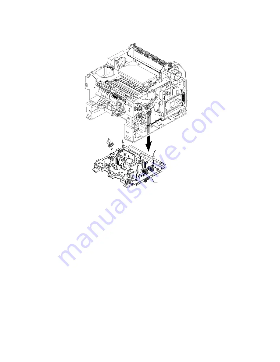
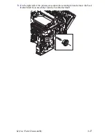
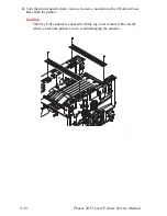
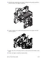
Disconnect 5 connectors (CN 1, CN 2, CN 3, CN 4, and CN 101) from the Power
Supply Board, then remove the Power Supply Board Assembly to a work surface
with the Power Supply up.
Reassembly Notes
Note
CN3 must be dressed correctly for reassembly. If CN3 is pulled too far
forward, assembly will be difficult.
1
-
Summary of Contents for Phaser 3425
Page 1: ...Service Manual P h a s e r L a s e r P r i n t e r 3425 ...
Page 2: ......
Page 14: ...xii Phaser 3425 Laser Printer ...
Page 20: ...xviii Phaser 3425 Laser Printer ...
Page 29: ...General Information 1 9 Consumables 1 Print Cartridge 1 ...
Page 48: ...2 14 Phaser 3425 Laser Printer Service Manual ...
Page 93: ...6 Chapter Adjustments and Calibrations In this chapter Margin Calibration Resetting NVRAM ...
Page 98: ...7 4 Phaser 3425 Laser Printer Service Manual ...
Page 144: ...8 46 Phaser 3425 Laser Printer Service Manual ...
Page 145: ...9 Chapter Parts Lists In this chapter Using the Parts List Print Engine Parts Xerox Supplies ...
Page 175: ...10 6 Phaser 3425 Laser Printer Service Manual ...
Page 179: ......
Page 180: ......


