


7
Controllers
Smart Pad
3
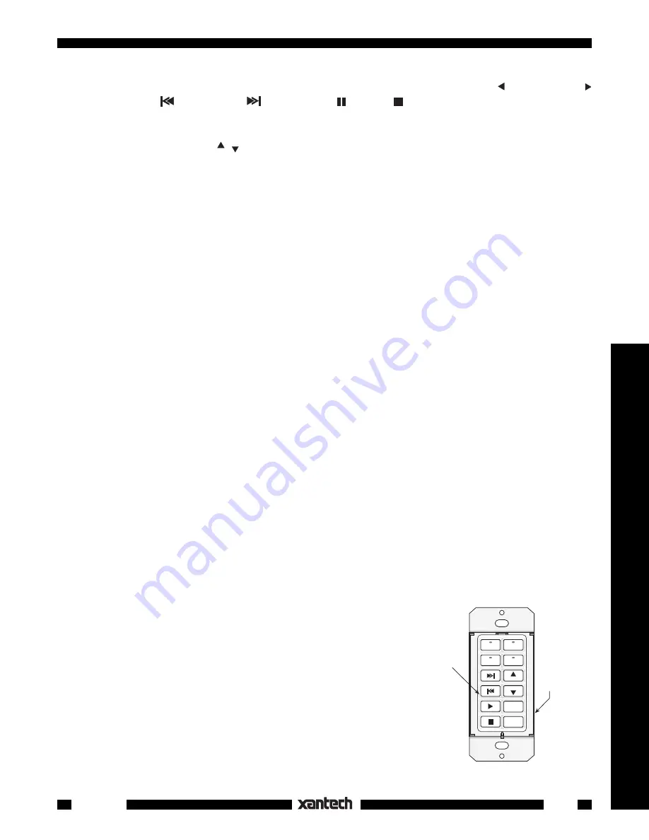
Fig. 5
Single Gang Button Assignments
NETWORK
RESTORE
COM PORT
B A 9 8 7 6
5
4
3
2
1
0
F
E
D
C
NETWORK
ADDRESS
WRITE
PROTECT
WRITE
READ
LM110
KM4
TAPE
TUNER
CD 1
CD 2
VOL
VOL
MUTE
OFF
13. When the TUNER functions are complete, press
TAPE
to select the tape bank. Using the Tape deck's
remote, program the seven
function
buttons that relate to this source as follows; (reverse play),
(forward play),
(fast rewind),
(fast forward), (pause), (stop), and
A/B
(selects A or B decks
of a dual cassette deck).
Common Commands
. The last group to be programmed are those that are
common
to each source or
bank. In this case, they will be
VOL
,
VOL
(volume up/down),
MUTE
and
OFF
.
14. Select each bank (source button), one at a time, and program these
function
buttons from the AM/
FM receiver's remote. Program the MUTE button with the speaker relay MUTE TOGGLE command.
See "
Speaker Relay
" section).
15. When you have completed all programming, you can
transfer
this whole command set to any number
of additional keypads (identically configured) that you may need in multiroom installations. Refer to the
"
Command Transfers
(Cloning)" section.
NOTE
: The
*
(asterisk) key is not used in this particular application.
A Single Gang Configuration
Many times a client wants a very simple keypad system with only a few basic functions or wishes to have
minimum intrusion into the room decor. In this case, a single gang application of the SmartPad
3
would be
appropriate. We will assume that the client has the following equipment and system requirements:
1. An AM/FM receiver and 4 sources:
TUNER
(AM/FM), two
CD
changers and a cassette
TAPE
deck.
2. When a source button is pressed, it must turn the AM/FM receiver ON along with the associated
source.
3. The keypad will have the following control function commands for each source:
TUNER:
Tuner Up/Down (scroll of preset stations).
CD 1 and CD 2
: Play, Track Forward/Reverse, Pause, Stop, Disc +.
TAPE
: Play Forward, Fast Forward/Rewind, Pause, Stop.
4. Speakers in the remote room must be mutable by using the
relay
in the
SmartPad
3.
This is the basic client specification for this application of the
SmartPad
3.
The next step is to determine what
SmartPad
3
modules
and keypad
buttons
are required to perform this
job, as follows:
1. Since there are 4
sources
, we can use the
KM4
Key Module, which provides 4 sources with status
indicators and 8 function keys.
2. Now, since this is a 1-gang configuration, we need an
LM110
Base Module into which we plug the
KM4
, as shown in
Fig. 5
.
3. The next step is to determine exactly what
buttons
are needed to carry out the control functions
needed.
4. Again, we begin this process by assigning the
Source
buttons first;
CD1,
TUNER
,
CD2
and
TAPE
. See
Fig. 5
.
5. Next, we assign the
function
control buttons based on the list of
functions given on page 12.
NOTE:
Most of the buttons for steps 4 and 5 are provided in the
SOURCE
and
FUNCTION
bags of buttons supplied with the
KM4
.
Buttons
CD 1
and
OFF
are not supplied but are available separately
from Xantech. They are listed in the dealer price list (along with all
buttons currently available for the
SmartPad
3
system). They should
be ordered at the same time as the other keypad parts.


