25
Controllers
Smart Pad
3
4-Conductor IR
Bus (network) Cables
(home runs)
TO EM110
L+
L–
R–
R+
SPEAKER
OUTPUT
L+
L–
R–
R+
AMPLIFIER
INPUT
+12V
IR OUT
ST
A
TUS
GND
PM110
Smart Pad
(rear view)
REMOTE ROOM
REMOTE ROOM
AMPLIFIER
IN
L+
L--
R--
R+
SPEAKER
OUT
LM110
Smart Pad
(rear view)
REMOTE ROOM
AMPLIFIER
IN
L+
L--
R--
R+
SPEAKER
OUT
LM110
Smart Pad
(rear view)
REMOTE ROOM
AMPLIFIER
IN
L+
L--
R--
R+
SPEAKER
OUT
LM110
Smart Pad
(rear view)
782-00
Power
Supply
490-00
Micro Link™ IR Receiver
To 120 VAC
(Unswitched)
9
8
1
2
3
4
5
6
7
VGGS
VGGS
VGGS
VGGS
VGGS
VGGS
VGGS
VGGS
VGGS
1
2
34
ON
OFF
BALANCE
AB
C
5678
GLOBAL
Z-ADJ
OFF
E-FLA
T
LAST
MAX-V
TRIM
MUTE
48
01
90
A0
30
B0
20
E0
70
F0
60
88
18
98
08
A8
38
B8
28
E8
78
F8
68
C8
58
D8
10
00
C0
50
D0
40
RC68 PR
OGRAMMER
0
1
2
3
4
5
6
7
To Emitters on
Controlled
Components
RC68 or RC68+
Handheld Programmer
CB18 Strip-IR™
Parallel Connecting Block
To System
"STATUS" Voltage
(
+
) (
–
)
12VDC
+12 VDC
GND
STATUS
IR IN
EMITTERS
IR
RCVR
789-44
CONNECTING BLOCK
®
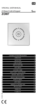
Fig. 31
PM110 to LMII0's Network Transfer (Cloning)
8. When done, set the
WRITE/PROTECT
switch to the
PROTECT
position on all keypads to prevent
unintended alteration or erasure.
Cloning Transfer Time
The time it takes to complete a cloning process depends on the amount of data required for the project and
the number of keypads. For instance, a small project using only 2k of memory transfers in 10 seconds to
a single keypad and an additional 1 to 2 seconds for every additional keypad. A very large project that uses
all of the available 32k of memory requires 105 seconds plus 10 seconds for every keypad that becomes
a clone. The maximum time, therefore, for 16 units to become clones would be 265 seconds (4 minutes,
25 seconds).
CAUTION:
With either COM Port or Network Transfer, the down-line unit(s) have no choice in what they
accept. Any commands that currently exist in the down-line units will be erased and completely replaced
by the new data.
All previous programming will be lost!
Clearing all Memory
If, for any reason, you wish to clear all programming from the keypad, set the
WRITE/PROTECT
switch to
the
WRITE
position and press
CLR MEM
button
twice
within 1 second (PM110). The active Source (bank)
LED will blink once to confirm the action.
• Bear in mind that
all previous programming will be lost!
• You may now proceed to reprogram the keypad from scratch.