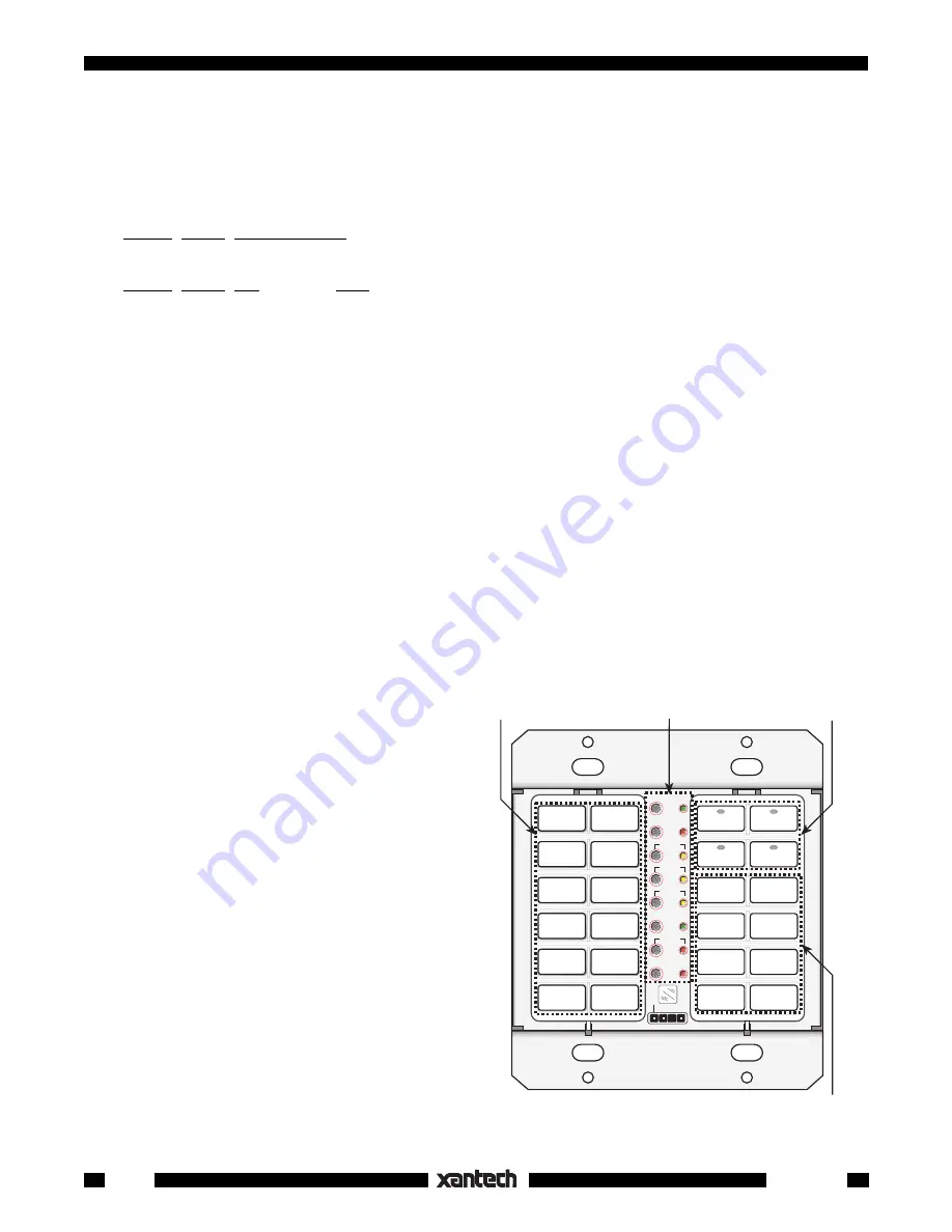
background image

16

Smart Pad

3

Fig. 18

Programming Reference

CLR MEM

RESTORE

NETWORK

PGM

TRNS

XFER

ERR

CNCL

FULL

DEL

EDIT

DELAY

SEQ

IR

STEP

C
O
M

B A 9 8 7 6

5

4

3

2

1

0

F

E

D

C

PROTECT

WRITE

NETWORK

ADDRESS

Programming

Buttons

Source (Bank)

Buttons

Function

Buttons

Function
Buttons

system or zone, is applied to the STATUS terminal on the rear of the keypad.

• See 

Figs. 3

 and 

6

 for typical connections for STATUS operation.

To take advantage of power management, program two or more sequence steps 

on each Source button

.

Typical command sequences, with 

Power first

, might be as follows:

a)

TUNER Source Sequence (3 steps):

Power, Delay, Tuner (source)

b)

CD Source Sequence (4 steps):

Power, Delay, CD (source), Play (CD play)

NOTE:

  If power management is 

not

 used (i.e. 3-wire hookups), a short jumper 

must

 be connected between

the 

STATUS

 and 

+12V

 terminals (see 

Fig. 17

).

This powers the source button LEDs so they will come on with the selected bank.  In this case, you  

must

put the system power command under an ON/OFF button (

not

 under the source buttons). 

The user will

then need to make two initial button presses, one for ON and one to select the Source

. (See also

NOTE

 top of page 24).

CAUTION: ZPR68 Installers. 


When programming the SmartPad

3

 for control of a ZPR68, you will need

to place the source select commands twice under each source button (in a 2-step sequence).  

This

permits sources to be selected after zone turn-on. (They would otherwise be blocked when zone turn-on
drives the 

STATUS

 line high).

Tiering

The SmartPad

3

 has the ability to program sequences or single commands onto two tiers or levels on any

Source or Function button. The 2nd tier is accessed by a "

Push & Hold

" of the tiered button.  This is very

useful when working with a limited number of buttons, such as single gang applications of the SmartPad

3

.

• After tiering is programmed, the 

1st tier

 is activated when the button is pressed for 

less than 1 second

.

• The

 2nd tier 

is accessed by a "

Press & Hold" 

of the same button for

 more than 1 second.

• The 

1st tier

 would typically be used to perform

an initial function, such as power on, source
selection, track skip, etc.

• The 

2nd tier

 would typically be used for a

secondary function that is related to the first tier,
such as music scan tiered on a track skip button
for CD.

1. To program the 

1st tier

 of a button, simply

program a single command or a sequence fol-
lowing steps 1 to 6 under "Sequence Program-
ming" (page 24).

 2. Press 

CNCL once

 to end the sequence, then

press the designated target key 

again

 in order

to activate the 

2nd tier

.  (If a 2nd tier is not

desired at this point, press CNCL a second time
to exit the Sequence mode.  The key will then
default to single tier operation).

3. Once in the 

2nd tier

, program the desired com-

mand or sequence (with delays if needed, fol-
lowing steps 2 to 6 below).  When finished, hit

CNCL


twice 

 to exit.

Summary of Contents for SmartPad3 LM110

Page 1: ...markings are included with each key module Many specialized versions are also separately available from Xantech Pre labeled buttons do not require any tedious insertion of small icon key caps Up to 8...

Page 2: ...have 12 buttons The last four have 11 buttons and include a cursor key cluster The module shells and buttons are available in white ivory and black An illustration and description of each follow KM1F...

Page 3: ...system into which the Key Modules are docked They contain the electronics for programming memory except the EM110 and include flanges for J box mounting An illustration and description of each follow...

Page 4: ...for the second Key Module 3 Now since this is a 2 gang configuration we need a PM110 Base Module into which we plug theKM1F and the KM4 Fig 1 shows the basic configuration Fig 1 Two Gang Configuratio...

Page 5: ...d commands and the Switched AC Outlet on the AM FM receiver Refer to Fig 3 We ll begin by teaching commands to the 4 source bank buttons TO EM110 L L R R SPEAKER OUTPUT L L R R AMPLIFIER INPUT 12V IR...

Page 6: ...d remote at the IR window and press it s play button 5 When the code is learned the PGM LED will flash again indicating it is ready to learn a command at another button 6 Press reverse scan button The...

Page 7: ...owing equipment and system requirements 1 An AM FM receiver and 4 sources TUNER AM FM two CD changers and a cassette TAPE deck 2 When a source button is pressed it must turn the AM FM receiver ON alon...

Page 8: ...tions in order for the source indicators and bank selections to operate 7 The keypad is now ready to be wired into the total system See Fig 6 Power may then be applied and we can proceed with the Prog...

Page 9: ...de is learned the SEQ LED will flash then go steady when you release the key on the remote 14 Press CNCL two times to exit the programming tier mode You can now test these learned commands But first b...

Page 10: ...changer an LD Laser Disc player a cassette TAPE deck a SAT Satellite receiver and a VCR 2 When a source button is pressed it must turn on the AM FM receiver and the associated source 3 The keypad mus...

Page 11: ...ly so that they can be custom configured with the desired button arrangements To assemble disassemble change and reassemble as desired proceed as follows Assembly Fig 11 Typical Key Module Assembly Ru...

Page 12: ...push hold tiering and sequence commands on any key Commands storable into 1 to 8 banks selectable by bank keys Editing of command sequences Intelligent Power Management inhibits first command in a seq...

Page 13: ...rols for programming only It will not repeat commands through the network system 13 COM Port RS232 signal compatible port for uploading or downloading to from a computer or transferring programmed con...

Page 14: ...e keypad defaults to bank 1 top left source button after each power up The unit is now ready for programming communications with a PC or cloning of programmed contents from one keypad to another Learn...

Page 15: ...d you want in the sequence 4 When the command has been learned the SEQ and PGM LEDs begin flashing and continue to flash until you release the key on the remote 5 The SEQ LED will then turn on steady...

Page 16: ...e button in a 2 step sequence This permits sources to be selected after zone turn on They would otherwise be blocked when zone turn on drives the STATUS line high Tiering The SmartPad3 has the ability...

Page 17: ...he keypad and have pressed CNCL to leave the programming modes you may send them to the controlled equipment simply by pressing the key that relates to them It is recommended that you test each set of...

Page 18: ...ED will come on steady 8 Input the IR command in the normal manner 9 When stored the PGM and SEQ LED will flash then go out You may now STEP to the next command NOTE You do not have to delete anything...

Page 19: ...ystem STATUS Voltage 12VDC 12 VDC GND STATUS IR IN EMITTERS IR RCVR 789 44 CONNECTING BLOCK Fig 20 Network Connection Diagram Programming for the Speaker Relay The relay will respond to commands for M...

Page 20: ...23 9 Test the IR commands by setting the rear switches on the RC68 to D8 the factory default Code Group setting for the SmartPad3 10 Pressing the 0 ON TOG IR command on the RC68 should cause the Relay...

Page 21: ...le TOGGLE command for instance would work well under the MUTE button in a system such as that in Figs 5 6 To program Toggle only proceed as follows 19 Begin by following steps 1 through 7 20 At this p...

Page 22: ...ressing D8 in the above process or by doing a CLR MEM Fig 15 Be aware that CLR MEM will erase all user programming Bank Tracking Programming Each Source bank key of the SmartPad3 can be programmed to...

Page 23: ...e 90 from the RC68 into the TUNER bank of the 1 keypad To do this follow the previous procedure steps 1 through 8 Now pressing CD or TUNER on either keypad will result in them tracking together Comman...

Page 24: ...y refer to Fig 31 To perform a Network Transfer proceed as follows 1 Connect up to 16 keypads onto a common IR bus network Refer to Fig 31 Be sure the system is powered up 2 If you have not already do...

Page 25: ...witch to the PROTECT position on all keypads to prevent unintended alteration or erasure Cloning Transfer Time The time it takes to complete a cloning process depends on the amount of data required fo...

Page 26: ...other wall mounted decorator style components A few things to keep in mind are as follows NETWORK RESTORE COM PORT B A9876 5 4 3 2 1 0 F E D C NETWORK ADDRESS WRITE PROTECT WRITE READ 1 3 4 LM110 1 1...

Page 27: ...er does not output IR commands Corrupted data in the 2nd keypad may have prevented a proper data transfer a Press the CLR MEM button twice on the 2nd keypad b Repeat the Command Transfers Cloning proc...

Page 28: ...signal output current 100 milliamps STATUS Terminal Power Management Turn on Voltage 5 to 30 volts DC 8mA 12V DC COM Port RS232 Signal Compatible Speaker Relay Stereo Speaker Pair Muting Contact Ratin...

Reviews: