


24
Smart Pad
3
B A 9 8 7 6
5
4
3
2
1
0
F
E
D
C
KEYPAD #1
(PM110)
Address 0
KEYPAD #2
(PM110 or LM110)
Address 1
KEYPAD #3, etc.
(PM110 or LM110)
Address 2, etc.
B A 9 8 7 6
5
4
3
2
1
0
F
E
D
C
B A 9 8 7 6
5
4
3
2
1
0
F
E
D
C
PROTECT
WRITE
PROTECT
WRITE
PROTECT
WRITE
NETWORK
ADDRESS
NETWORK
ADDRESS
NETWORK
ADDRESS
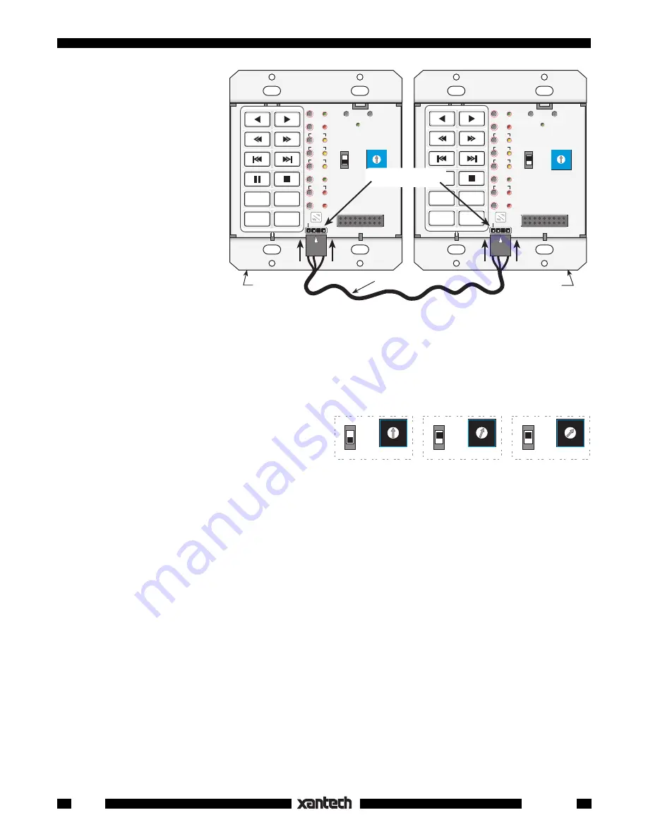
Fig. 30
Set Each Keypad to a Unique Network Address
6. When done, set the
W R I T E / P R O T E C T
switch to the
PROTECT
position on all keypads.
Network Transfer
Network Transfer greatly fa-
cilitates the cloning of keypads
when you have a number of
keypads on the same IR bus
(network), up to a maximum of
16. This would apply to multi-
room single zone systems, or
to multi-zone systems where
you may have two or more
keypads per zone. Even in
multi-zoned systems, you
could make up a temporary
common IR network by using
one or two CB18 Strip-IR's,
CLR MEM
RESTORE
NETWORK
PGM
TRNS
XFER
ERR
CNCL
FULL
DEL
EDIT
DELAY
SEQ
IR
STEP
C
O
M
B A 9 8 7 6
5
4
3
2
1
0
F
E
D
C
PROTECT
WRITE
NETWORK
ADDRESS
CLR MEM
RESTORE
NETWORK
PGM
TRNS
XFER
ERR
CNCL
FULL
DEL
EDIT
DELAY
SEQ
IR
STEP
C
O
M
B A 9 8 7 6
5
4
3
2
1
0
F
E
D
C
PROTECT
WRITE
NETWORK
ADDRESS
RANDOM
A/B
DISC
–
DISC
+
PM110
3' cable
COM PORTS
PM110
RANDOM
A/B
DISC
–
DISC
+
(Programmed Unit)
(Un-programmed Unit)
UP
UP
Fig. 29
PM110 to PM110 COM Port Transfer (Cloning)
rather than cloning each one individually (refer to
Fig. 31
).
To perform a Network Transfer, proceed as follows:
1. Connect up to 16 keypads onto a common IR bus (network). Refer to
Fig. 31
. Be sure the system
is powered up.
2. If you have not already done so, set each
SmartPad
3
to a
unique NETWORK ADDRESS
(
Fig. 30
) such as 0, 1, 2, 3, etc.
NOTE:
The programmed keypad from which
the commands are cloned could actually be a
17th keypad, if necessary, and it does not need
to have a unique address.
CAUTION
: All unprogrammed keypads
must
be set to a different address for cloning to be successful.
3. Set the
WRITE/PROTECT
switch to
PROTECT
on the programmed unit (keypad #1) and press it's
RESTORE
button.
4. On each of the other keypads, set the
WRITE/PROTECT
switch to
WRITE
(
Fig. 30
) and press the
RESTORE
button.
NOTE:
Once you have performed steps 1 through 4, you can make transfers with or without the key
modules installed on the PM110's or LM110's.
5. Press the
XFER
button on the programmed unit. Its PGM and SEQ LEDs will flash slowly.
6. Press the
SEQ
button. The PGM, SEQ, NETWORK and one Source (bank) LED will flash quickly on
the unprogrammed units until the transfer completes.
NOTE:
If transfer does not complete, the process stops and the sending unit will flash it's ERR LED
at a 2 Hz rate. If this occurs, remove power from all units, reapply power and try again.
7. If, for any reason you do not want all units to receive the cloning signal, simply set the
WRITE/
PROTECT
switch to
PROTECT
on such units.
NOTE:
You may stop the cloning process at any time by pressing any keypad's RESTORE button.


