630140_1
XFIRE_1200_GB
_Service_R
‐
em
otion
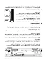
Once
the
con
tro
l
unit
cover
has
been
removed
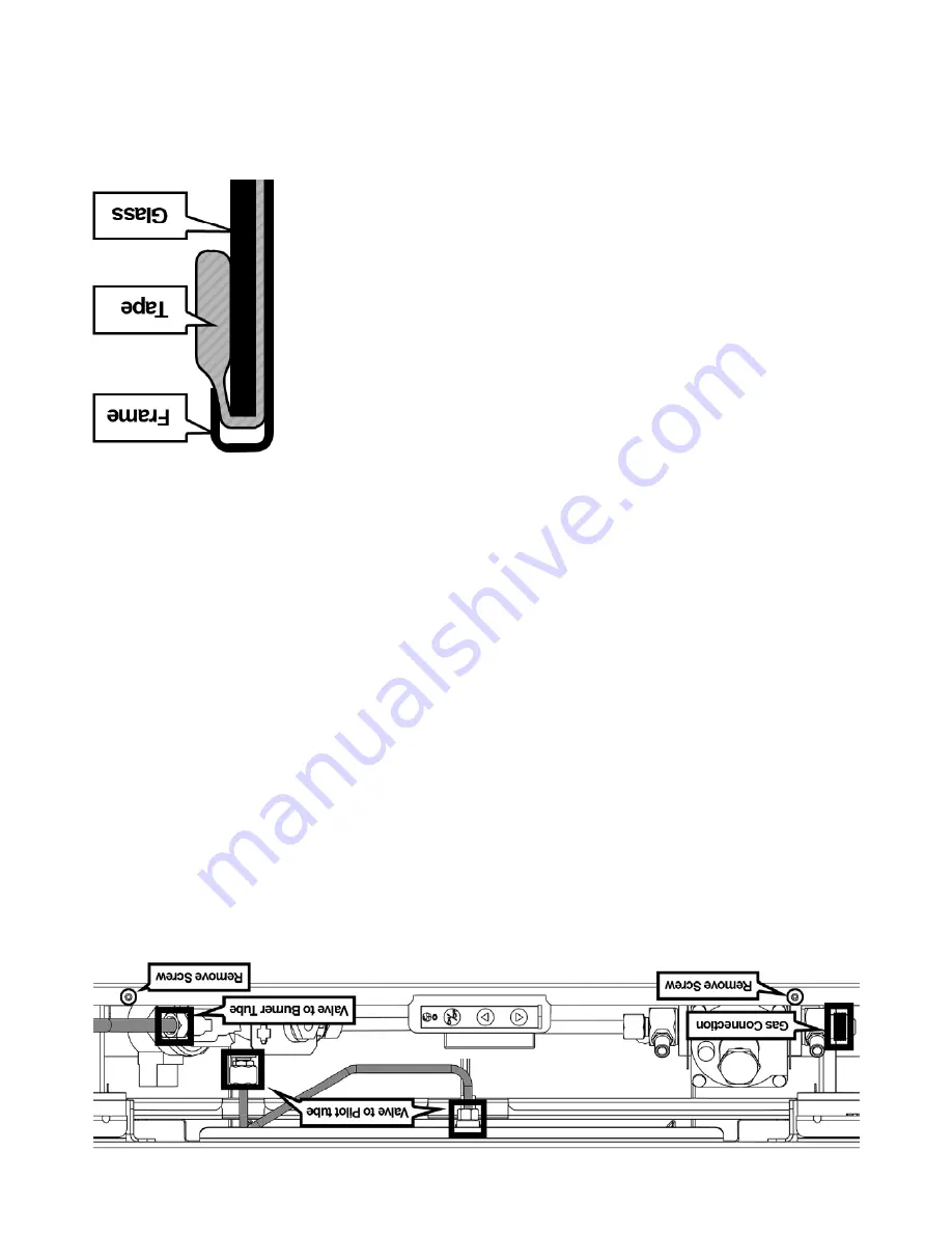
the
main
gas
connection,
Valve
to
Pilot
tube,
and
Valve
to
Burner
tubes
shou
ld
be
disconnecte
d.
Push
the
thermocouple
down
from
inside
the
firebox
to
disconnect
from
pilot
asse
mbly.
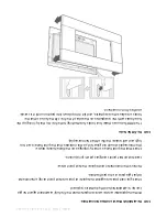
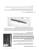
Once
the
two
screws
pictured
above
are
removed
the
tray
is
free
to
be
lifted
(e
nsuring
that
all
wiring
is
clear
from
sheet
metal)
up
15mm
to
clear
the
metal
edge
and
pulled
towards
you.
If
the
thermocouple
needs
to
be
replaced
unplug
from
tray
and
unscrew
from
end
of
valve.
It
can
then
be
replaced
with
the
replacemen
t
thermo
couple.
Ensure
that
the
replacemen
t
thermo
couple
is
pushed
fully
home
–
This
may
requ
ire
substan
tia
l
force.
A
click
shou
ld
be
felt.
Other
components
on
the
control
tray
can
be
repla
ced
when
necessary
while
tray
is
separate
from
the
firep
lace.
When
replacing
the
tray
,
make
sure
to
reco
nnect
all
gas
pipes
tigh
tly
and
using
sealant
wher
e
required.
6.0
Check
Glass
Assembly:
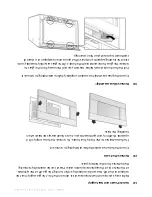
Check
that
the
glass
assembly
(R
emoved
in
section
3.0)
for
damage
to
glass
or
sealin
g
tape.
If
the
glass
has
any
visible
damage
it
must
be
replaced
befo
re
use.
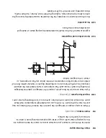
Ensure
the
tape
which
seals
the
glass
against
the
firebox
is
in
the
correct
posit
ion
(shown
to
the
right)
and
that
the
glass
is
secu
re
inside
the
metal
frame
and
free
from
movement.
7.0
Clean
Pilot
and
Main
Burner
Jets:
With
the
burner
removed
the
burner
jet
is
now
accessible.
Remove
the
jet
and
clean
it
using
an
approp
riate
method
,
such
as
using
a
micro
drill
or
co
mpresse
d
air.

