630140_1
XFIRE_1200_GB_Manual_R
‐
emotion
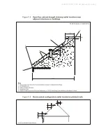
Figure C.2
Minimum dimensions of room-sealed chimney outlet positions
(refer to Figure C.8)
Symbol Location
(kW input expressed in net)
Minimum dimensions
Natural
Draught
Fanned
Draught
A
A)
Directly below an opening, air brick, opening windows, (0-7 kW)
etc (>7-14 kW)
(>14-32 kW)
(>32-70 kW)
300 mm
600 mm
1 500 mm
2 000 mm
300 mm
B
A)
Above an opening, air brick, opening window, etc (0-7 kW)
(>7-14 kW)
(>14-32 kW)
(>32-70 kW)
300 mm
300 mm
300 mm
600 mm
300 mm
C
A)
Horizontally to an opening, air brick, opening windows, (0-7 kW)
etc (>7-14 kW)
(>14-32 kW)
(>32-70 kW)
300 mm
400 mm
600 mm
600 mm
300 mm
D
Below temperature-sensitive building components, e.g. plastic gutters,
Soil pipes or drain pipes
300 mm
75 mm
E
Below eaves
300 mm
200 mm
F
Below balconies or car port roof
600 mm
200 mm
G
From vertical drain pipe or soil pipe
300 mm
150 mm
B)
H
C)
From an internal or external corner
600 mm
300 mm
I
Above ground, roof or balcony level
300 mm
300 mm
J
From a surface facing the terminal
600 mm
600 mm
K
From a terminal facing the terminal
600 mm
1 200 mm
L
From an opening in the car port (e.g. door, window) into the dwelling
1 200 mm
1 200 mm
M
Vertically from a terminal on the same wall
1 500 mm
1 500 mm
N
Horizontally from a terminal on the same wall
300 mm
300 mm
O
From the wall on which the terminal is mounted
0
0
P
From a vertical structure on the roof
N/A
N/A
Q
Above intersection with roof
N/A
300 mm
NOTE N/A = Not applicable.
A)
In addition, for temperature and structural reasons, the terminal should not be nearer than 150mm (fanned draught)
or 300mm (natural draught) to an opening in the building fabric formed for the purpose of accommodating a built-in
element such as a window frame (see Figure C.9). Separation distances are linked to the rated heat inputs as shown.
B)
This dimension may be reduced to 75mm for appliances of up to 5 kW heat input.
C)
The reference to external corners does not apply to building protrusions not exceeding 450mm, such as disused
chimneys on external walls for; fanned draught appliances; natural draught appliances not exceeding a net input
of 7 kW; any other appliances if detailed in the appliance manufacturer’s instructions.
If using a horizontal flue terminal, a guard must be fitted to the terminal where
it is located less than 2m above the ground, above a balcony or flat roof to
which people have access.
This guard is available from SpecFlue, UK FreeFone 0800 9020220,
Interna44 1787 880333
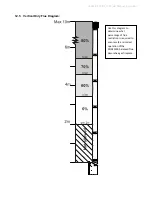
12.10 Supporting the flue system:
Wall straps are required to fix the flue system in place for each installation. This will ensure
that no undue strain is placed on flue components once installed.
For a flue offset or horizontal run, it is recommended that wall straps be used to the flue
system with a spacing of 900mm between straps. Plumbers strapping / tape can be used to
connect the wall straps to the building structure where there are large distances between
the support point and the anchor point.
For vertical flue runs it is recommended that wall straps be used to anchor the flue system
with a spacing of 1200mm between straps.

