


MedWeld 5000 Overview
1 - 2
MedWeld 5000 Technical Reference Manual
M-032170
the timer unit. It also provides fault detection. Finally, mid-frequency
conversion reduces the size of the welding transformer and the power
line demand required.
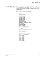
•
SPC data (Group, bin and part number)
This data can be reviewed this data with a programming device
(such as the WTC DEP-100S Hand-Held Terminal), or use it for
data analysis by programs such as WTC’s WebVIEW.
•
Sequence number executed
•
Transformer turns ratio
•
Minimum, average and maximum DC bus voltage
•
Minimum, average and maximum secondary current
•
C-factor
•
Average on-time
•
Number of cycles in the last weld
•
Line cycle or milisecond timing
•
Stepper data and
•
Desired constant current.
The MFDC is different from “traditional” single-phase welding and
high-frequency DC welding in the following ways:
•
There is essentially no power factor or impedance in high-
frequency welding that corresponds to the power factor issues of
AC welding. The power factor is high and constant, and the welder
transformer secondary circuit is direct current (DC).
•
The welding transformer depends on the applied voltage and circuit
resistance. It is generally independent of the magnetic effects of the
secondary circuit. (Magnetic material in the secondary is not a
consideration.)
•
Given a constant applied voltage, the weld current depends
primarily on the resistance of the weld itself. (Welds with different
resistances will result in different weld current.)
Summary of Contents for MedWeld 5000
Page 2: ...MedWeld 5000 Technical Reference Manual Modified 1 31 06 M 032170...
Page 6: ...MedWeld 5000 Technical Reference Manual Modified 1 31 06...
Page 38: ...Installing the MedWeld 5000 2 12 MedWeld 5000 Technical Reference Manual M 032170...
Page 82: ...Advanced Software Features 5 12 MedWeld 5000 Technical Reference Manual M 032170...
Page 120: ...Hardware Troubleshooting 9 10 MedWeld 5000 Technical Reference Manual M 032170...


