


MedWeld 5000 Overview
MedWeld 5000 Technical Reference Manual
1 - 3
M-032170
Timer Unit
The timer unit sends a gating signal to the inverter, as required by the
weld schedule. The timer unit will tell the inverter when to pull in the
main power isolator, allowing the inverter to provide welding current.
The timer unit performs all the weld timing functions required to
execute a weld schedule:
•
Checks input signals (provided through DeviceNet) and reacts to
them accordingly.
•
Operates the output signals based on the weld schedule.
•
Sends the gating signals to the inverter as required by the weld
schedule.
•
Adjusts the firing signal, based on the control’s firing mode, to
provide a constant supply despite changes in the welding
environment.
•
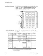
LEDs on the timer unit module indicate control status. These
indicators are described below:
If the LEDs do not turn on during the weld schedule, the timer unit may
be faulty, or the control may be sequencing in No Weld mode.
PWR
This LED lights to indicate that power is being supplied to the
timer unit and it is functioning normally.
RUN
These LEDs light to indicate that the timer unit card has sent
the logic level gating signal to the inverter. These LEDs are
normally off. They should only turn on when current is
provided by the weld schedule.
SEQ
These 2 LEDs light to indicate that communication is
occurring on the MedLAN channel.
NS
These LEDs light to indicate that communication is taking
place between the data entry panel (DEP) and the timer unit
card.
EN
This LED lights when the control is ready to weld. This means
that the control will provide current under these conditions:
•
No faults exist
•
The Control Stop Input is not active (off is active)
•
The control is in Weld Mode
•
The WCU is synchronized with the welding bus and
•
The Inverter is ready to weld (the IRTW signal is high).
Summary of Contents for MedWeld 5000
Page 2: ...MedWeld 5000 Technical Reference Manual Modified 1 31 06 M 032170...
Page 6: ...MedWeld 5000 Technical Reference Manual Modified 1 31 06...
Page 38: ...Installing the MedWeld 5000 2 12 MedWeld 5000 Technical Reference Manual M 032170...
Page 82: ...Advanced Software Features 5 12 MedWeld 5000 Technical Reference Manual M 032170...
Page 120: ...Hardware Troubleshooting 9 10 MedWeld 5000 Technical Reference Manual M 032170...


