


Fault Conditions
8 - 10
PMMK Software F04100
M-032170
Fault Probable
Cause
Remedy
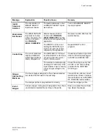
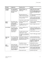
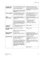
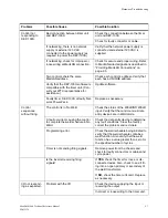
LOW POWER LINE:
AC line voltage is too low. (Primary
Current and
Primary Voltage firing modes).
~or~
Three or more mid-frequency half-
cycles ended due to maximum on
time reached. Check 'On-time' dis-
play.
Check AC power line voltage, Check
input phases for bad
connections.
SOFT
OVERCURRENT:
At least two (but less than six) mid-
frequency half-cycles ended because
inverter reached Soft Overcurrent, or
Maximum Primary Current Limit.
Inverter was able to limit current in the
Safe Operating Area.
Check Weld Transformer
secondary load, secondary resistance
may be abnormally low. Set Soft
Overcurrent Limit higher if there is no
problem with secondary resistance.
Maximum Primary Current Limit may
indicate that the weld load is poorly
matched to the inverter with the
installed welding transformer, or that
the inverter is too small for the appli-
cation.
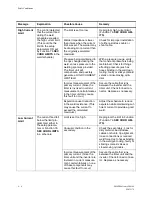
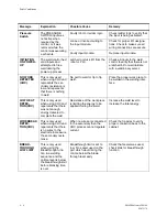
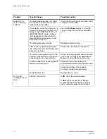
CURRENT
REGULATION:
The inverter could not reach the
requested current (programmed cur-
rent plus any additions from stepper
program) during three or more con-
secutive mid-frequency half-cycles.
NOTE: This fault is not generated at
the beginning of a weld to avoid false
detection during current ramp-up.
Check Weld Transformer
secondary load. Secondary resis-
tance may be abnormally high.
Requested current may be too high
due to programmed value plus step-
per program.
WELDING
TRANSFORMER:
Six consecutive mid-frequency half-
cycles, or four consecutive mid-fre-
quency half-cycles of the same polar-
ity ended because the Maximum
Primary Current Limit was exceeded.
This may indicate a shorted second-
ary diode in the weld transformer.
Check the Weld Transformer for
shorted secondary diodes (follow the
manufacturer’s recommended proce-
dure
~or~
Replace the weld transformer with a
known good unit.
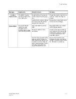
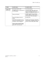
DC BUS
OVERVOLTAGE:
The DC bus voltage is too high, based
on an abnormally high AC Line volt-
age
Check the AC line voltage.
INVERTER BUS:
The DC fell more than 40% from the
value measured at the start of weld
time. This is calculated from the AC
Line Voltage reading.
Check the AC power line for voltage
sags, missing phases or loose con-
nections.
Summary of Contents for MedWeld 5000
Page 2: ...MedWeld 5000 Technical Reference Manual Modified 1 31 06 M 032170...
Page 6: ...MedWeld 5000 Technical Reference Manual Modified 1 31 06...
Page 38: ...Installing the MedWeld 5000 2 12 MedWeld 5000 Technical Reference Manual M 032170...
Page 82: ...Advanced Software Features 5 12 MedWeld 5000 Technical Reference Manual M 032170...
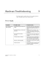
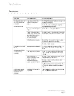
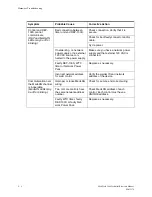
Page 120: ...Hardware Troubleshooting 9 10 MedWeld 5000 Technical Reference Manual M 032170...


