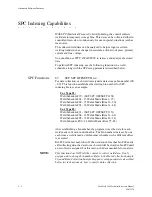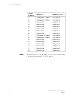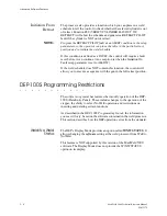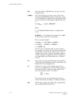
Setup Parameters
MedWeld 5000 Technical Reference Manual
6 - 5
M-032170
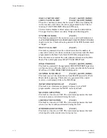
LOW POWER LINE
(FAULT)
The inverter generates this fault condition when it detects that it was not
able to provide sufficient line voltage in the constant primary voltage
firing mode. (The Firing Mode setup parameter is set to PRI
VOLTAGE.)
SOFT OVERCURRENT:
(FAULT) (ALERT)
The inverter generates this condition when it detects that at least two
(but no more than six) mid-frequency half-cycles were terminated
because the inverter reached the programmed Soft Overcurrent limit, or
Maximum Primary Current setup parameter.
CURRENT REGULATION:
(FAULT) (ALERT)
When using the PRI CURRENT firing mode, the inverter will generate
this fault condition if it detects that it could not obtain the requested
current during three or more consecutive mid-frequency half-cycles.
In all firing modes, the current set point is reached before the masking
interval ends on 4 or more consecutive highfrequency half-cycles. In the
PRIMARY I firing mode, the Maximum on or Flux Limit is reached on
4 or more consecutive high-frequency half-cycles.
WELDING TRANSFORMER:
(FAULT)
This fault is generated when either six or more consecutive half-cycles
or more than four consecutive mid-frequency half-cycles of the
same
polarity end because the Maximum Primary Current setup parameter
was exceeded. This fault condition is generated from the PRI
VOLTAGE firing mode.
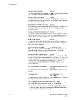
DC BUS OVER VOLTAGE:
(FAULT)
This fault condition is generated when the inverter detects that the
voltage on the DC bus exceeded the inverter’s maximum safe operating
range for two consecutive midfrequency cycles.
INVERTER BUS:
(FAULT)
This fault is generated when the inverter detects that the DC bus voltage
dropped by more than 40% of the value measured at the start of weld
time. On detecting this condition, the inverter immediately disregards
firing signals from the weld processor. The inverter then executes the
error shut-down procedure.
INVERTER OVER TEMP:
(FAULT)
This fault indicates that either the energy storage capacitors on the
inverter chill plate or the chill plate itself exceeded the recommended
temperature.
OUTPUT GROUND:
(FAULT)
This fault indicates a current imbalance between the two output
terminals of the regulator.
Summary of Contents for MedWeld 5000
Page 2: ...MedWeld 5000 Technical Reference Manual Modified 1 31 06 M 032170...
Page 6: ...MedWeld 5000 Technical Reference Manual Modified 1 31 06...
Page 38: ...Installing the MedWeld 5000 2 12 MedWeld 5000 Technical Reference Manual M 032170...
Page 82: ...Advanced Software Features 5 12 MedWeld 5000 Technical Reference Manual M 032170...
Page 120: ...Hardware Troubleshooting 9 10 MedWeld 5000 Technical Reference Manual M 032170...


