


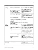

Fault Conditions
PMMK Software F04100
8 - 7
M-032170
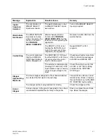
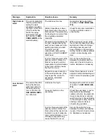
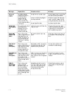
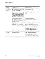
Control in
No Weld
The control moved
from Weld Mode to
No Weld Mode while
executing a weld
schedule.
Robot or PLC de-
activated the WELD/NO
WELD input.
Check robot or PLC to verify
that the input is being held
HIGH throughout the schedule.
Use the DEP
I/O Status
display
to observe the status of this
input.
Data entry device is pro-
grammed in No Weld mode.
Verify that the data entry device
is in Weld Mode.
Loose or incorrect wiring to
the input module.
Check for proper I/O designa-
tions. Check to make sure all
wiring connections are secure.
Faulty input or output module.
Replace I/O module.
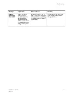
High C-
Factor
The C-factor read
during the weld part
of the schedule
exceeded the value
programmed in
Function #92.
Unusual conditions in the
secondary.
Check for causes of shunting or
conducting water.
The High C-factor limit was
programmed too low.
Raise the high C-factor limit.
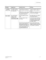
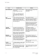
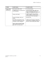
Low C-Factor
The C-factor read
during the weld part
of the schedule fell
below the value
programmed in
Function #92.
Unusual conditions in the
secondary.
Check for worn cables, loose
connections, low air pressure or
other causes of decreased sec-
ondary current.
The Low C-factor limit was
programmed too high.
Lower the Low C-factor limit.
Tips closing too slowly, due
to a dirty or poorly-lubricated
cylinder.
Check for sticking gun cylinder.
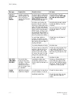
Heat Cycle
Limit
The control reached
the programmed limit
of consecutive weld
cycles where conduc-
tion was detected.
Weld schedule programming
was incorrect, or the heat
cycle limit in the setup param-
eters was set too low.
Lower the number of cycles
when the weld control is firing.
Your application does not need
the Heat Cycle Limit setup
parameter. To disable this
parameter, set it to 0.
Faulty timer unit card.
Replace timer unit card.
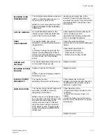
Weld
Proceed
WELD PROCEED
input did not become
active when required
by the control, or it
was removed while
the control was exe-
cuting a schedule.
Faulty robot or ladder logic.
Check ladder logic to verify that
the input is being activated.
Loose or incorrect wiring to
the input module.
Check for proper I/O designa-
tions. Check to make sure all
wiring connections are secure.
Faulty input module.
Replace input module.
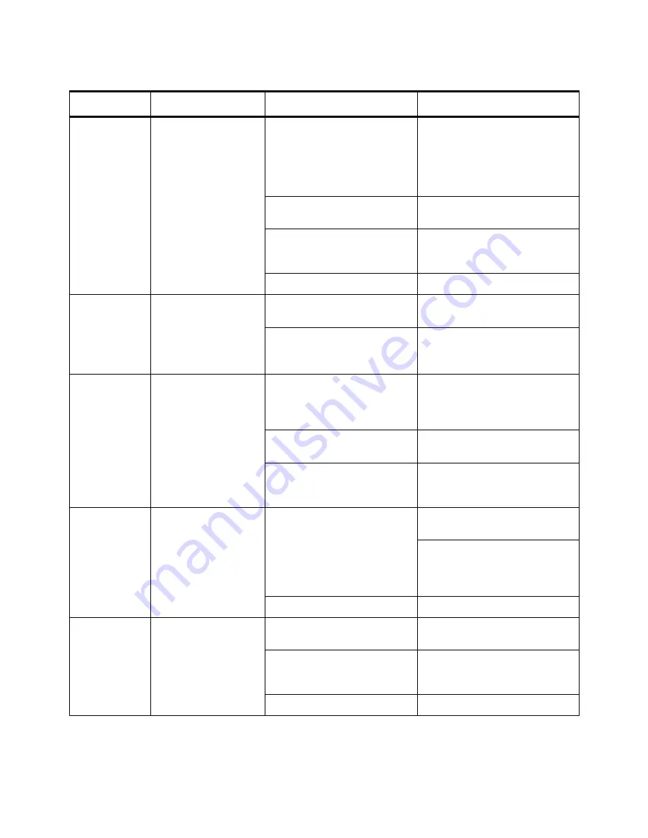
Message
Explanation
Possible Cause
Remedy
Summary of Contents for MedWeld 5000
Page 2: ...MedWeld 5000 Technical Reference Manual Modified 1 31 06 M 032170...
Page 6: ...MedWeld 5000 Technical Reference Manual Modified 1 31 06...
Page 38: ...Installing the MedWeld 5000 2 12 MedWeld 5000 Technical Reference Manual M 032170...
Page 82: ...Advanced Software Features 5 12 MedWeld 5000 Technical Reference Manual M 032170...
Page 120: ...Hardware Troubleshooting 9 10 MedWeld 5000 Technical Reference Manual M 032170...


